
Optical fiber temperature sensor based on nano fluorescent material and measuring system

A nano-fluorescence and optical fiber temperature technology, applied in the field of optical fiber sensing, can solve the problems of low temperature sensitivity and low optical signal intensity, and achieve the effect of simple production, simple structure, and reduction of temperature cross-sensitivity problems.

Pending Publication Date: 2021-10-08
TIANJIN UNIV
View PDF9 Cites 0 Cited by
  • Summary
  • Abstract
  • Description
  • Claims
  • Application Information

AI Technical Summary

Problems solved by technology

[0004] In order to overcome the disadvantages of low optical signal intensity and low temperature sensitivity caused by optical loss in existing sensors, based on the above technical problems, the present invention proposes an optical fiber temperature sensor and measurement system based on nano-fluorescent materials, using fluorescent The advantages of high photothermal stability, high signal-to-noise ratio, and no background noise interference of the material enable stable and high-sensitivity temperature measurement

Method used


Image

  • Optical fiber temperature sensor based on nano fluorescent material and measuring system
  • Optical fiber temperature sensor based on nano fluorescent material and measuring system
  • Optical fiber temperature sensor based on nano fluorescent material and measuring system

Examples


Embodiment Construction

[0038] The technical solutions of the present invention will be further described in detail below in conjunction with the accompanying drawings and specific embodiments.

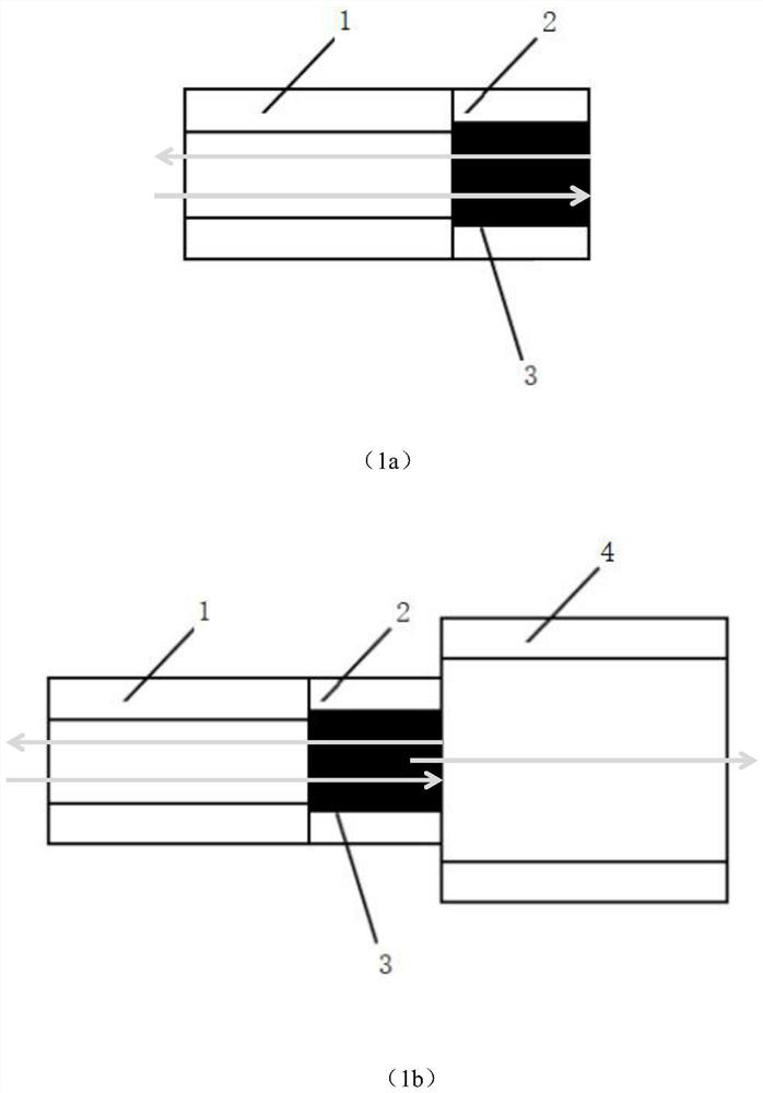
[0039] Such as figure 1 As shown, it is a structural schematic diagram of the optical fiber temperature sensor based on the nano fluorescent material of the present invention. The optical fiber temperature sensor comprises a first multimode optical fiber 1 with a flat end face connected to each other and a hollow core optical fiber 2 , and a hollow core cavity of the hollow core optical fiber 2 is filled with a fluorescent material body 4 . Among them, the hollow-core optical fiber 2 selects an optical fiber with an inner diameter of about 75 microns and an outer diameter of about 125 microns, and the first multimode optical fiber 1 selects an optical fiber with a core diameter of about 62.5 microns and an outer diameter of about 125 microns. The optical fiber temperature sensor structure of the present inv...


PUM

PropertyMeasurementUnit
diameteraaaaaaaaaa
lengthaaaaaaaaaa

Abstract

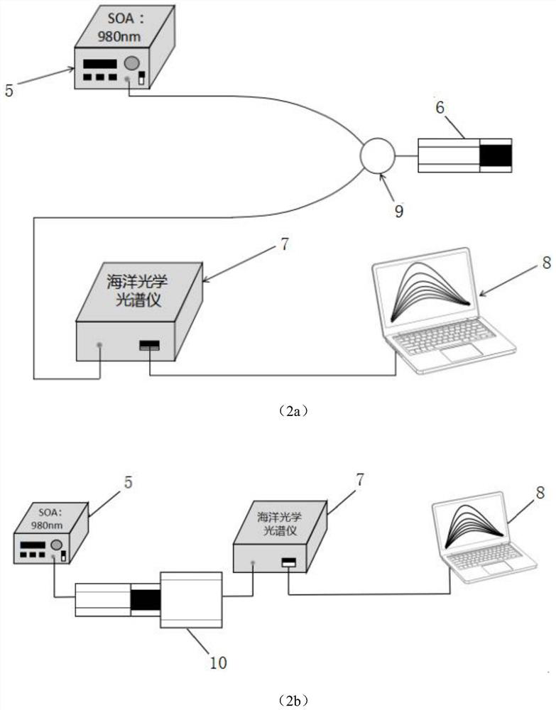
The invention discloses an optical fiber temperature sensor based on a nano fluorescent material and a measuring system. The optical fiber temperature sensor comprises a multimode optical fiber (1) and a hollow-core optical fiber (2) which are connected with each other and have flat end surfaces, and a fluorescent material body (4), wherein the structure of the optical fiber temperature sensor is divided into (a) a reflection type optical fiber temperature sensor structure and (b) a transmission type optical fiber temperature sensor structure. According to the invention, an optical fiber temperature sensing and measuring system based on a nanometer fluorescent material is built by using the optical fiber temperature sensor based on the nanometer fluorescent material as a sensing unit, and comprises a 980 nm pump light source (5), a reflection type optical fiber temperature sensor (6) based on a nano fluorescent material or a transmission type optical fiber temperature sensor (10) based on the nano fluorescent material, an optical fiber coupler (9), a spectrograph (7) and a computer (8), wherein temperature measurement and processing are realized by utilizing a reflection spectrum or laser; and compared with the prior art, the optical fiber temperature sensor of the invention has higher temperature measurement sensitivity.

Description

technical field [0001] The invention relates to the technical field of optical fiber sensing, in particular to an optical fiber temperature sensor based on nano fluorescent materials and a measurement system thereof. Background technique [0002] In many engineering application fields, such as civil engineering, aerospace and composite materials, etc., it is necessary to obtain the information of the temperature change of the device. The most common temperature measurement uses such as fiber optic fluorescence temperature sensor, fiber grating temperature sensor, interference fiber optic temperature sensor, refractive index fiber optic temperature sensor, birefringence fiber optic temperature sensor, absorption fiber optic temperature sensor and based on Rayleigh scattering, Brillouin Distributed temperature sensors for scattering and Raman scattering, etc. [0003] In 1985, neodymium glass was used as a sensitive material to make a temperature sensor based on fluorescence ...

Claims


Application Information

Patent Timeline
Patent Type & Authority Applications(China)
IPC IPC(8): G01K11/32
CPCG01K11/32
Inventor 王双蔡维安华平壤刘铁根江俊峰
Owner TIANJIN UNIV
Learn More