
Rail fixing device with function of vertical guidance

A fixed device and track technology, applied in the field of rail transit, can solve problems such as hidden safety hazards, affecting driving safety, and the inability of steel rails to withstand upward force, so as to improve lateral rigidity and safety, high comfort and safety, and improve vehicle safety. Small horizontal shaking effect

Active Publication Date: 2013-05-08
QINGDAO CREATE ENVIRONMENT CONTROL TECH +1
View PDF12 Cites 10 Cited by
  • Summary
  • Abstract
  • Description
  • Claims
  • Application Information

AI Technical Summary

Problems solved by technology

[0003] (1) The rails fixed by this type of rail fixing device cannot withstand the upward force, so there are safety hazards in use
For example, when the foundation subsides, the rail fixing device will drop along with the foundation, but because the rail is continuous, the rail will not move down with it, which will cause the failure of the support of the rail fixing device to the rail, leaving room for traffic safety. Hidden danger;
[0004] (2) During use, the force point will change when the force is applied, there will be wear between the elastic body and the rail, and the stability will decrease after the elastic part is worn;
[0005] (3) The rail is only in contact with the elastic body, so the elastic body must provide both vertical support and lateral restraint for the rail, but in order to ensure the effect of vibration and noise reduction, the elastic body in this type of rail fixing device must have Elasticity, so the lateral stiffness of the rail is small, and the rail will inevitably shake from side to side during driving, resulting in serious wear of the rail, and even large-scale corrugation in some cities, which seriously affects driving safety;
[0006] (4) Since the rail is in a suspended state, the safety reserve is very small, and there is no secondary protection. Once the elastic body is damaged, the position of the rail will lose control in all directions, and the train will derail. Therefore, this kind of rail fixing device has higher maintenance requirements , when the maintenance is not in place, it will affect driving safety
[0007] Cologne eggs and other high-elastic high-elastic fasteners also have similar problems. Since the lateral stiffness of the fastener is closely related to the vertical stiffness, the vertical stiffness decreases continuously with the increase in vibration damping requirements, and the lateral stiffness also decreases, resulting in The lateral vibration of the wheel and rail increases, and the lateral shaking of the train increases, which affects the comfort of the train and aggravates the wear of the rail. In severe cases, it even causes abnormal corrugation of the rail, which increases the workload of rail maintenance and seriously shortens the life of the rail.
[0008] The above-mentioned defects have greatly affected the normal use of the rails and caused great economic losses. The market urgently needs a new type of rail fixing device that can overcome the above-mentioned deficiencies

Method used


Image

  • Rail fixing device with function of vertical guidance
  • Rail fixing device with function of vertical guidance
  • Rail fixing device with function of vertical guidance

Examples


Embodiment 1

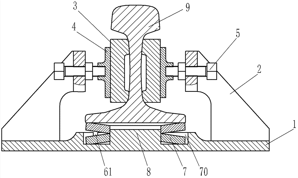
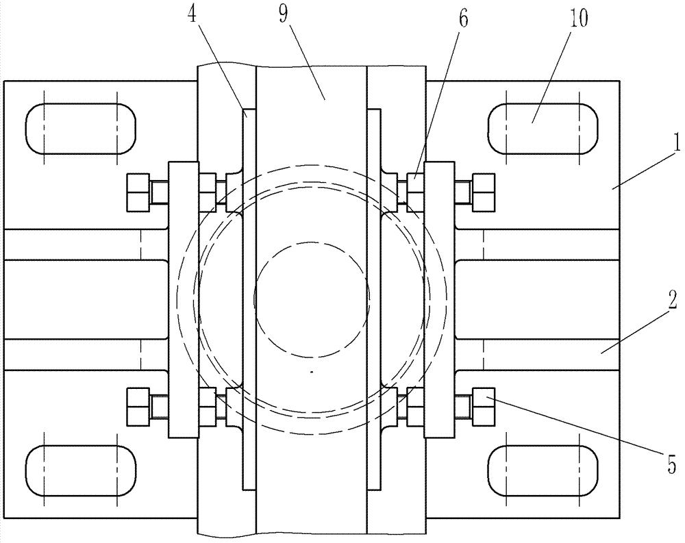
[0060] Such as figure 1 , figure 2 The present invention shown has a vertically guided rail fixing device, comprising a base 1 made of cast steel material, and further comprising guide assemblies and vertical support elements. The guide assembly includes a guide element 3 and a guide bracket 2 located on both sides of the rail waist of the rail 9. A pressure plate 4 and a position adjustment bolt 5 are also arranged on the body of the guide bracket 2. The guide element 3 is pressed tightly on the The rail waist surface of the rail 9. Among them, there are two guide brackets 2, which are made of the same material as the base 1, and are cast into one body with the base 1; the guide element 3 is made of nylon material, and the surface of the guide element is provided with grooves, which are only on the top and bottom of the rail waist of the rail 9. The part is in close contact with the rail. The vertical supporting element is made of a metal spring, specifically a metal disc...

Embodiment 2

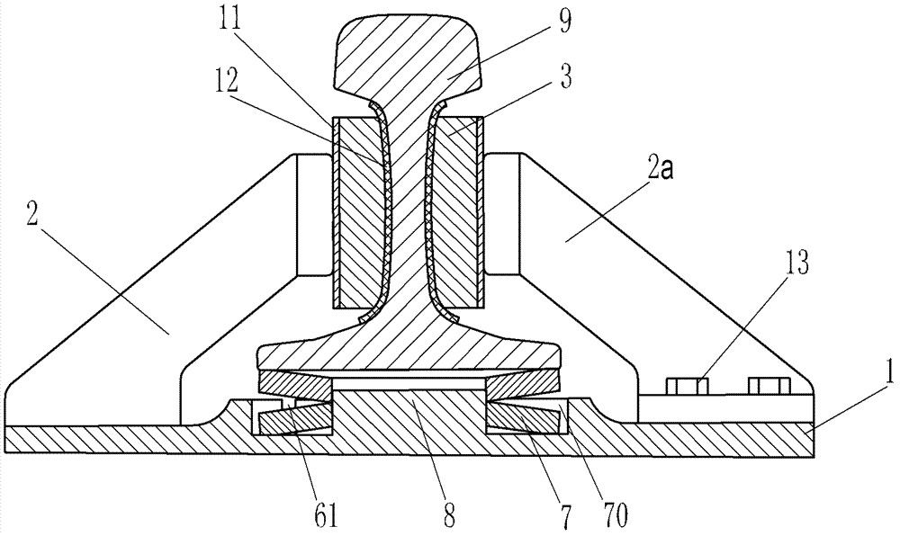
[0068] Such as image 3 , Figure 4 As shown, the present invention has a vertically guided rail fixing device. The difference from Embodiment 1 is that the guide assembly includes a guide bracket 2 cast integrally with the base 1 and a detachable guide bracket 2a, wherein the guide bracket 2a It is fixed on the base 1 by fasteners 13 . Since a detachable guide bracket 2a is provided, the rail fixing device with vertical guidance of the present invention can be easily assembled with the rail 9 and its relative position adjusted, so the guide bracket 2 and 2a can be directly used to press the guide element 3 tightly On the rail waist, no other position adjustment devices are provided. The guide element 3 is made of PVC material, and its mating surface with the rail adopts profiling design, and keeps in close contact with the rail waist surface of the entire rail. The lateral stiffness of the guide elements is 400 kN / mm. Due to the high rigidity of the guide element 3, in or...

Embodiment 3

[0075] Such as Figure 5 , Figure 6 The difference between the present invention with a vertically oriented rail fixing device and the second embodiment is that the buffer protection pad 12 is made of elastic polyurethane polymer material. In addition, in order to make the disc spring 7 evenly stressed, a support plate 15 is provided between the disc spring 7 and the rail 9, and a hardened steel pipe 8 is provided in the middle of the support plate 15 to ensure the centering of the disc spring 7, and it is also used as an emergency support , The gap between the bottom surface of the emergency support 8 and the bottom surface of the base 1 should be greater than or equal to the maximum deformation of the rail 9 during normal operation. Corresponding to the position of the emergency supporting member 8 , a through hole 16 is also provided on the base 1 . Bosses 50 are partially provided on both sides of the base 1 corresponding to the position of the guide bracket 2a, and the...


PUM


Abstract

The invention relates to rail accessories, in particular to a rail fixing device with the function of vertical guidance. The rail fixing device comprises a base disposed on a sleeper. The base is fixedly connected with the sleeper through anchor bolts. The rail fixing device is characterized by further comprising a guide component and a vertical support element. The guide component comprises a guide element and a guide support located on two sides of a rail web of a steel rail. The transverse stiffness of the guide element is at least 120KN / mm. The guide element is tightly contacted with the steel rail at least from the top and bottom of the rail web of the steel rail and transversely limits the steel rail. The guide element is clamped by the guide support. Slide contact surfaces are arranged between the guide element and the guide support and are parallel to the vertical direction of the steel rail, and the guide element and the guide support can slide relative to each other along the vertical direction of the steel rail. The vertical support element is located below the steel rail and has elastic supporting capacity at least in the vertical direction of the steel rail. The guide component on two sides of the rail web is used for guiding, the vertical support element below the steel rail is used for supporting and power consuming, and accordingly stressing stability of the steel rail is improved effectively and the safety is better.

Description

technical field [0001] The invention belongs to the field of rail transportation, and relates to a rail accessory, in particular to a rail fixing device with both the fastener function and the vibration reduction function. Background technique [0002] Today's rail transit continues to develop in the direction of high speed and heavy load, which brings convenience to people's production and life, but also brings many problems, especially the environmental pollution caused by track noise. In order to reduce the noise of the track, technicians have developed many vibration and noise reduction products, including rail fixing devices with vibration and noise reduction functions. For example, the patent application No. 200480019707.1 and the patent application No. The track fastening device that can realize the suspension of the railway track, it utilizes the bracket to support the rail head on the elastic member. In this fastening system, a gap is designed under the rail bottom...

Claims


Application Information

Patent Timeline
Patent Type & Authority Applications(China)
IPC IPC(8): E01B9/54E01B9/58E01B9/62
Inventor 孔祥斐尹学军雷晓燕曲洪啸任静刘伟宁曾向荣
Owner QINGDAO CREATE ENVIRONMENT CONTROL TECH
Learn More