Eureka AIR delivers breakthrough ideas for toughest innovation challenges, trusted by R&D personnel around the world.

Metal tubing two-end molding mechanism

A technology for metal pipes and forming mechanisms, applied in metal processing equipment, other manufacturing equipment/tools, feeding devices, etc., can solve the problems of reduced work efficiency, inconvenient processing, and inability to insert pipe benders, etc., to improve work efficiency, The structure is reasonable and reliable, and the effect of meeting the requirements of end forming

Active Publication Date: 2013-05-08
FOSHAN TIANJIAN MECHANICAL CO LTD
View PDF10 Cites 3 Cited by
  • Summary
  • Abstract
  • Description
  • Claims
  • Application Information

AI Technical Summary

Problems solved by technology

[0002] It is known in the industry that although the forming mechanism on an ordinary cutting machine can form at one time and reduce the number of processing times, it generally can only form the front end of the pipe, which makes its design still have disadvantages. For example, the pipe after chip-free cutting will have a little Shrink the mouth, so that the mandrel of the pipe bender cannot be inserted, which will cause inconvenience in processing and reduce work efficiency

Method used


Image

  • Metal tubing two-end molding mechanism
  • Metal tubing two-end molding mechanism
  • Metal tubing two-end molding mechanism

Examples


Embodiment Construction

[0016] The present invention will be further described below in conjunction with specific examples.

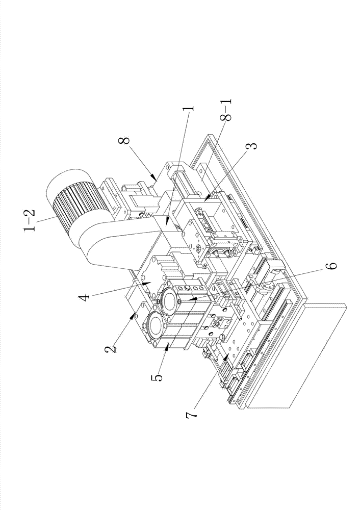
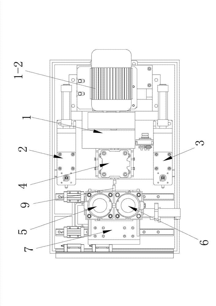
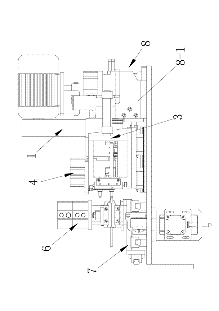
[0017] See attached figure 1 to attach Figure 4 As shown, the forming mechanism at both ends of the metal pipe described in this embodiment includes a cutting mechanism 1, a first translational forming ejector mechanism 2, a second translational forming ejector mechanism 3, a first forming clamping mechanism 4, The second forming clamping mechanism 5, the third forming clamping mechanism 6, the horizontal transposition mechanism 7, and the forming advancing mechanism 8, wherein, the material opening mechanism 1, the first translation forming ejecting mechanism 2, and the second translation forming ejecting mechanism 3. The first forming clamping mechanism 4 is respectively installed on the forming propulsion mechanism 8, which is driven by the forming propulsion mechanism 8 to realize the overall translational advancement. At the same time, in the advancing direction of the ...


PUM


Abstract

The invention provides a metal tubing two-end molding mechanism which comprises a second molding clamping mechanism, a third molding clamping mechanism, a horizontal switchover mechanism, a molding push mechanism, a cutting mechanism, a first translation molding ejection mechanism, a second translation molding ejection mechanism and a first molding clamping mechanism. The cutting mechanism, the first translation molding ejection mechanism, the second translation molding ejection mechanism and the first molding clamping mechanism are respectively arranged on the molding push mechanism. The first translation molding ejection mechanism and the second translation molding ejection mechanism are arranged at two sides of the first molding clamping mechanism in the pushing direction of the molding push mechanism. The cutting mechanism is arranged behind the first molding clamping mechanism. The horizontal switchover mechanism is arranged in front of the first molding clamping mechanism. A tube front end punch is arranged on the horizontal switchover mechanism. The second molding clamping mechanism and the third molding clamping mechanism are respectively arranged on the horizontal switchover mechanism and distributed in the movement direction of the horizontal switchover mechanism. The metal tubing two-end molding mechanism is capable of not only chambering and molding the front end of a tube, but also chambering and molding the rear end of the tube.

Description

technical field [0001] The invention relates to the technical field of pipe forming equipment, in particular to a metal pipe two-end forming mechanism. Background technique [0002] It is known in the industry that although the forming mechanism on an ordinary cutting machine can form at one time and reduce the number of processing times, it generally can only form the front end of the pipe, which makes its design still have disadvantages. For example, the pipe after chip-free cutting will have a little Shrink the mouth, so that the mandrel of the pipe bender cannot be inserted, which will cause inconvenience in processing and reduce work efficiency. Therefore, due to the requirements of actual working conditions, there is an urgent need for a mechanism capable of forming both ends of the pipe. Contents of the invention [0003] The object of the present invention is to overcome the deficiencies of the prior art, and provide a forming mechanism for both ends of metal pipe...

Claims


Application Information

Patent Timeline
IPC IPC(8): B23P23/02B21D41/02B21D43/00
Inventor 黄伟明何明伦
Owner FOSHAN TIANJIAN MECHANICAL CO LTD
Why Eureka
Eureka Blog
Learn More