
Polyhedron funnel type air inlet unit for CVD (chemical vapor deposition) equipment and CVD equipment

A gas inlet device and funnel-type technology, applied in the direction of gaseous chemical plating, metal material coating process, coating, etc., can solve the adverse effects of material growth speed, crystal quality and raw material utilization rate, complex CVD growth process, Affect crystal quality and other issues to achieve the effect of reducing wall parasitic reactions and easy and effective decomposition

Active Publication Date: 2013-04-24
SUZHOU INST OF NANO TECH & NANO BIONICS CHINESE ACEDEMY OF SCI
View PDF4 Cites 1 Cited by
  • Summary
  • Abstract
  • Description
  • Claims
  • Application Information

AI Technical Summary

Problems solved by technology

However, the CVD growth process is extremely complex, involving transport and multi-component, multi-phase chemical reactions, usually dozens of chemical reactions occur, and only chemical reactions on the substrate surface can produce crystals with good crystal quality
[0004] At present, the air intake device of CVD equipment can basically realize the two kinds of reaction sources are sent into the reaction chamber separately, but because the gas mixing and the pre-reaction between the gases are a pair of contradictions: when the gas is mixed uniformly, the pre-reaction between the gases The reaction is large; when the pre-reaction between gases is small, it is difficult for the gases to mix evenly
There are the following problems: the two reaction sources are mixed before they reach the substrate surface, and pre-reaction occurs at high temperature, which affects the crystal quality; Detrimental effect on quality as well as raw material utilization

Method used


Image

  • Polyhedron funnel type air inlet unit for CVD (chemical vapor deposition) equipment and CVD equipment
  • Polyhedron funnel type air inlet unit for CVD (chemical vapor deposition) equipment and CVD equipment
  • Polyhedron funnel type air inlet unit for CVD (chemical vapor deposition) equipment and CVD equipment

Examples


Embodiment Construction

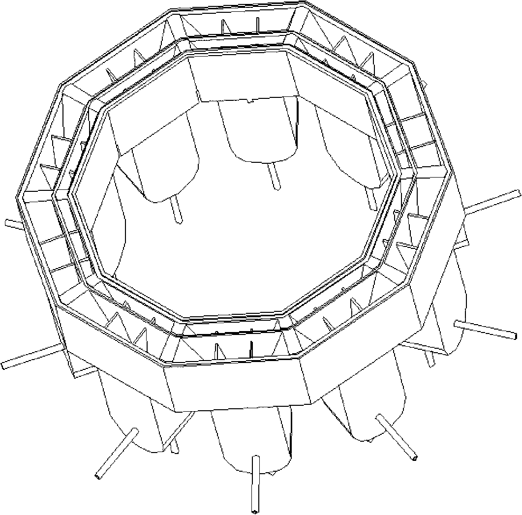
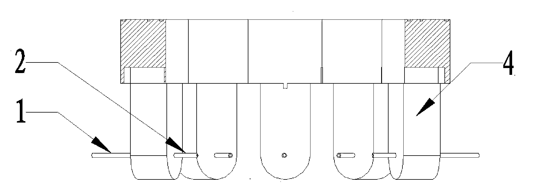
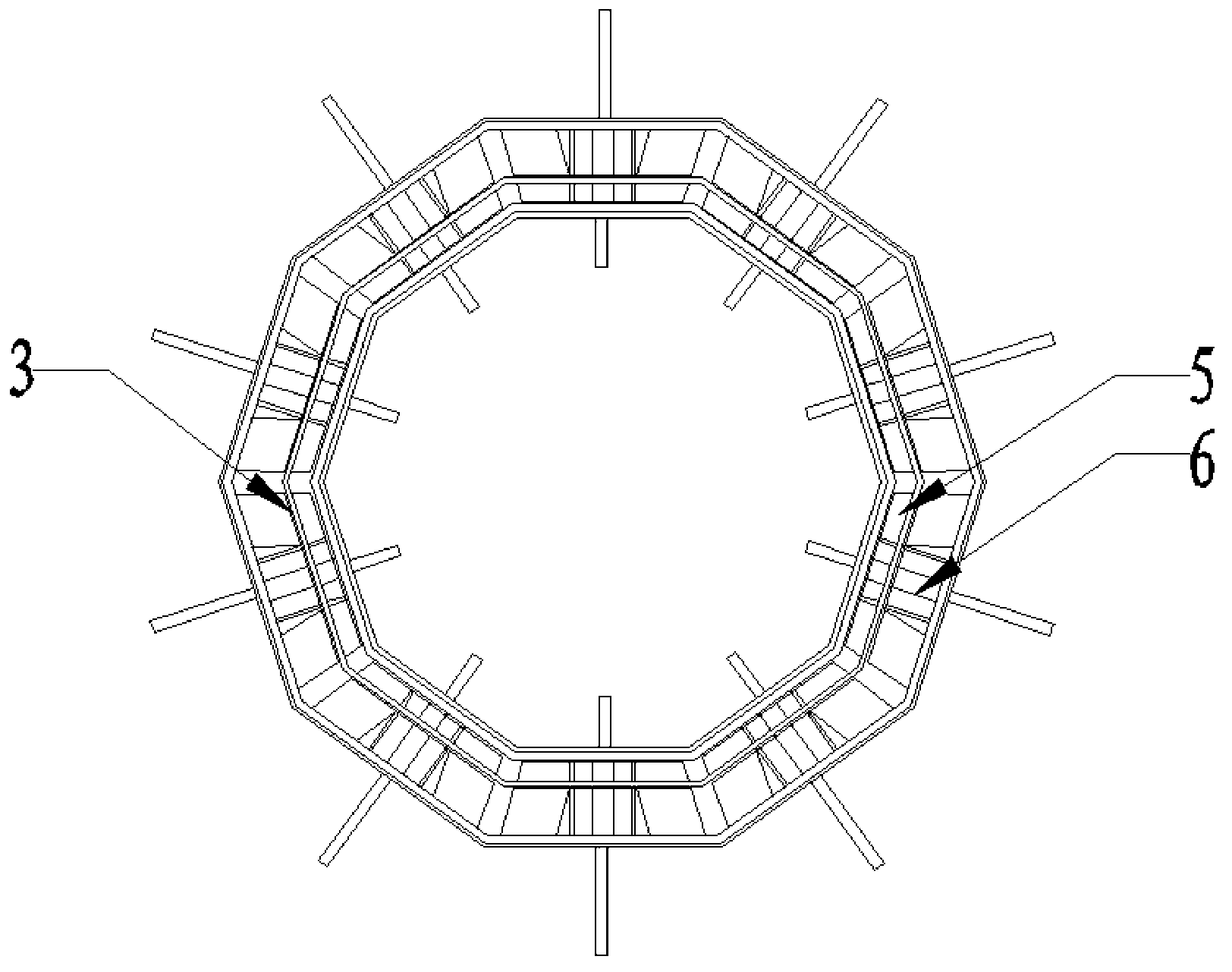
[0031] One aspect of the present invention aims to provide a multi-faceted funnel-type inlet device for CVD equipment, which includes a plurality of funnel bottle inlet nozzles with the same structure and connected around the center to form a polyhedron. The layer baffles are completely isolated into inner and outer air intake chambers, and the inner and outer air intake chambers are also communicated with the first air intake pipe and the second air intake pipe respectively.

[0032] Taking the application of the multi-faceted funnel-type gas inlet device in the growth process of Group III-V semiconductor devices as an example, the aforementioned inner and outer layers of gas inlet chambers can be used as a group V gas inlet chamber and a group III gas inlet chamber respectively.

[0033] Further, the aforesaid funnel bottle inlet nozzle may include two parts, the bottle body and the bottle mouth, wherein one end of the bottle body is a closed end, the other end is fixedly con...


PUM

PropertyMeasurementUnit
thicknessaaaaaaaaaa

Abstract

The invention discloses a polyhedron funnel type air inlet unit for CVD (chemical vapor deposition) equipment and CVD equipment. The air inlet unit is of a polyhedron shaped structure and comprises a plurality of funnel bottle air inlet nozzles which are distributed in a ring shape, wherein each funnel bottle air inlet nozzle is provided with an inner layer air inlet cavity and an outer layer air inlet cavity which are isolated from each other; and the inner layer air inlet cavity and the outer layer air inlet cavity are communicated with a first air inlet pipe and a second air inlet pipe, respectively. The CVD equipment comprises the above polyhedron funnel type air inlet unit. With the adoption of the polyhedron funnel type air inlet unit and the CVD equipment, various reaction source gases are independently fed into a reaction chamber, thus various reaction sources are mixed fully before reaching a substrate and the pre-reaction is inhibited effectively; meanwhile, the reaction gas can also evenly disperse into a large area from a small area with a certain angle so as to achieve laminar flow; and the gas supply which is even and can be switched rapidly is provided to the reaction chamber. With the adoption of the polyhedron funnel type air inlet unit and the CVD equipment, the speed and the quality of the epitaxial growth of the CVD equipment and the raw material using ratio can be effectively improved.

Description

technical field [0001] The invention relates to semiconductor thin film deposition equipment, in particular to a multi-faceted funnel-type gas inlet device and CVD equipment for chemical vapor deposition (CVD) equipment. Background technique [0002] Chemical vapor deposition equipment is the core equipment for the preparation of compound semiconductor epitaxial materials. It has obvious advantages in the preparation of superlattice and quantum wells. It has been used in the large-scale industrial production of the optoelectronics industry. In the development situation, indispensable strategic high-tech semiconductor equipment. [0003] When CVD equipment epitaxially grows crystal materials, various source materials and carrier gases enter the reaction chamber through different pipes. Among them, the source materials are V-group source gases and III-group source gases, which participate in chemical reactions and the products contain the original material components; The gas...

Claims


Application Information

Patent Timeline
Patent Type & Authority Applications(China)
IPC IPC(8): C23C16/455
Inventor 王劼张立国范亚明张泽洪
Owner SUZHOU INST OF NANO TECH & NANO BIONICS CHINESE ACEDEMY OF SCI
Learn More