
Multilevel condensation water heating system

A technology for heating systems and condensed water, applied in lighting and heating equipment, preheating, supplementary water supply, etc., can solve the problems of increasing pipe spacing, long desulfurization flue space, pipe fitting corrosion, etc., to increase flue gas resistance, Avoid the effect of excessive dust accumulation

Inactive Publication Date: 2013-04-17
沈兴财
View PDF6 Cites 2 Cited by
  • Summary
  • Abstract
  • Description
  • Claims
  • Application Information

AI Technical Summary

Problems solved by technology

In addition, due to the flue gas sucking back that may be caused by the desulfurization operation, the desulfurization slurry is poured back into the flue at the entrance of the absorption tower, and the slurry deposits to block the flue gas circulation channel between the pipe fittings and cause corrosion to the pipe fittings
Therefore, it is not only necessary to use corrosion-resistant materials to make pipe fittings, but also to increase the distance between pipes, which requires a long space for the desulfurization flue, which makes the flue at the entrance of the absorption tower too long, making it difficult to arrange the flue

Method used


Image

  • Multilevel condensation water heating system
  • Multilevel condensation water heating system
  • Multilevel condensation water heating system

Examples


Embodiment 1

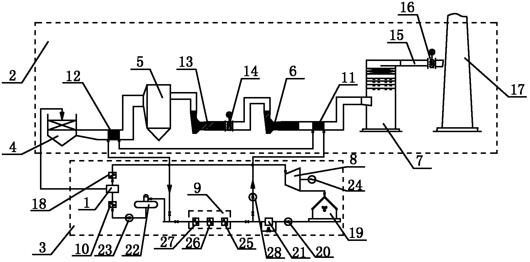
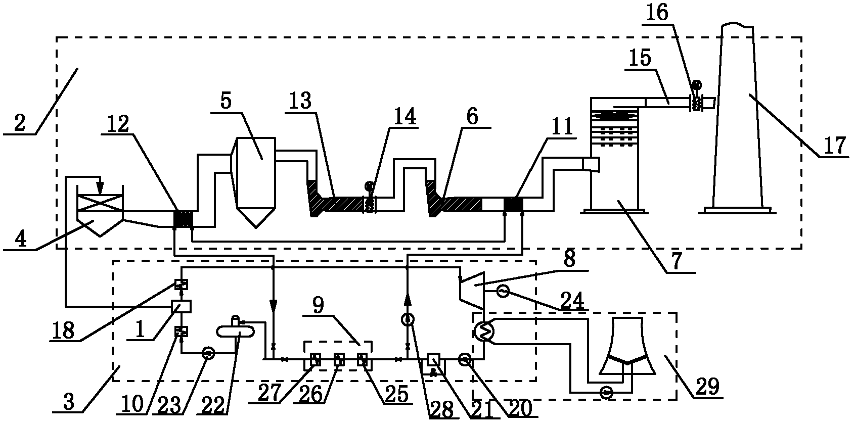
[0031] Embodiment 1 of the present invention: as figure 1As shown, a multi-stage condensate heating system includes a boiler 1, a tail flue gas treatment system 2 and a flue gas waste heat recovery system 3, and the tail flue gas treatment system 2 includes an air preheater 4, a dust collector 5, and a booster fan 6. Absorption tower 7, induced draft fan 13, induced draft fan outlet baffle 14, clean flue 15, clean flue gas baffle 16 and chimney 17, one end of induced draft fan 13 is connected with dust collector 5, and the other end of induced draft fan 13 is set There is an induced draft fan outlet baffle 14, and the induced draft fan outlet baffle 14 is connected with the absorption tower 7 through the original flue, and the absorption tower 7 is connected with one end of the clean flue gas baffle 16 through the clean flue 15, and the clean flue baffle 16 The other end is connected to the chimney 17; the flue gas waste heat recovery system 3 includes a steam turbine 8, a lo...

Embodiment 2

[0034] Embodiment 2 of the present invention: as figure 1 As shown, a multi-stage condensate heating system includes a boiler 1, a tail flue gas treatment system 2 and a flue gas waste heat recovery system 3, and the tail flue gas treatment system 2 includes an air preheater 4, a dust collector 5, and a booster fan 6. Absorption tower 7, induced draft fan 13, induced draft fan outlet baffle 14, clean flue 15, clean flue gas baffle 16 and chimney 17, one end of induced draft fan 13 is connected with dust collector 5, and the other end of induced draft fan 13 is set There is an induced draft fan outlet baffle 14, and the induced draft fan outlet baffle 14 is connected with the absorption tower 7 through the original flue, and the absorption tower 7 is connected with one end of the clean flue gas baffle 16 through the clean flue 15, and the clean flue baffle 16 The other end is connected to the chimney 17; the flue gas waste heat recovery system 3 includes a steam turbine 8, a l...

Embodiment 3

[0037] Embodiment 3 of the present invention: as figure 1 As shown, a multi-stage condensate heating system includes a boiler 1, a tail flue gas treatment system 2 and a flue gas waste heat recovery system 3, and the tail flue gas treatment system 2 includes an air preheater 4, a dust collector 5, and a booster fan 6. Absorption tower 7, induced draft fan 13, induced draft fan outlet baffle 14, clean flue 15, clean flue gas baffle 16 and chimney 17, one end of induced draft fan 13 is connected with dust collector 5, and the other end of induced draft fan 13 is set There is an induced draft fan outlet baffle 14, and the induced draft fan outlet baffle 14 is connected with the absorption tower 7 through the original flue, and the absorption tower 7 is connected with one end of the clean flue gas baffle 16 through the clean flue 15, and the clean flue baffle 16 The other end is connected to the chimney 17; the flue gas waste heat recovery system 3 includes a steam turbine 8, a l...


PUM


Abstract

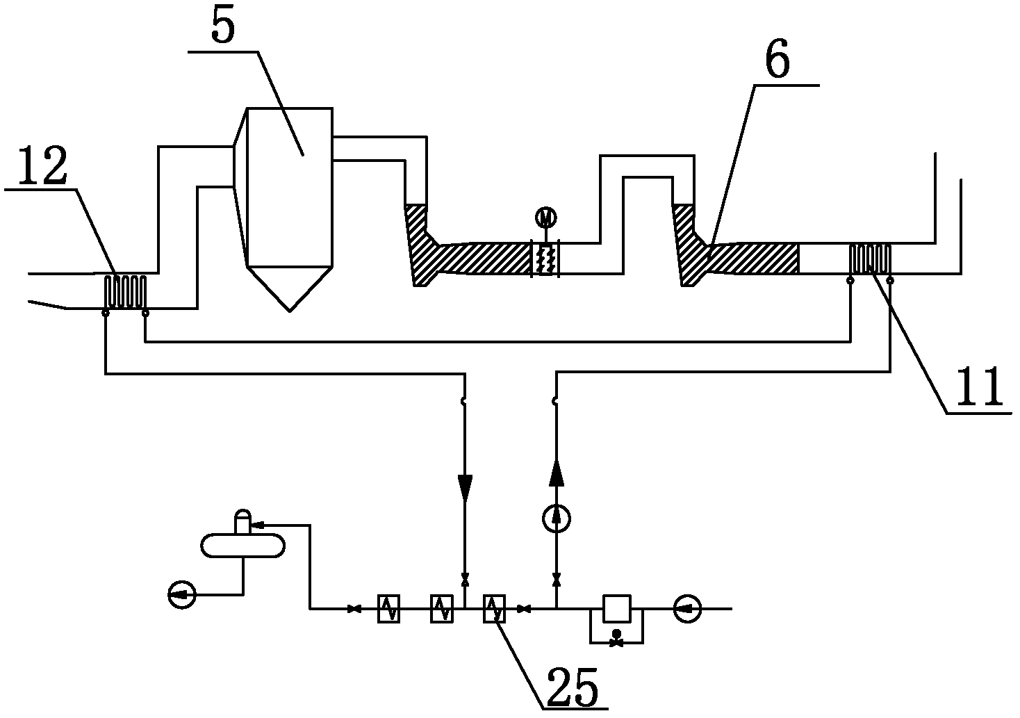
The invention discloses a multilevel condensation water heating system which comprises a boiler, a tail smoke processing system and a smoke waste heat recycling system. The steam output end of the boiler is respectively connected with an air preheater and a turbine. The condensation water input end of the boiler is connected with a high pressure heater, a first level air water heat exchanger is arranged in a smoke channel where a booster fan is connected with an absorption tower, a second level air water heat exchanger is arranged in a smoke channel where the air preheater is connected with a dust remover, the input end of the first level air water heat exchanger is connected with the condensation water input end of a low pressure water heater, the output end of the first level air water heat exchanger is connected with the input end of the second level air water heat exchanger through a pipe, and the output end of the second level air water heat exchanger is connected with the condensation water output end of the low pressure heat exchanger. The multilevel condensation water heating system adopts multilevel heat exchange, can completely utilize smoke waste heat, and can effectively resolve the problem that a traditional low temperature heater is apt to ash blocking, easy to corrode, easy to abrade and high in construction cost.

Description

technical field [0001] The invention relates to a condensed water heating system, in particular to a multi-stage condensed water heating system. Background technique [0002] SO2 is one of the main air pollutants faced by human beings. SO2 in the atmosphere can cause serious harm to the human body, organisms and the natural environment. Low concentrations of sulfur dioxide can affect the respiratory system of animals and humans. When the concentration is high, it can cause bronchitis, Asthma, for people with respiratory diseases and heart disease, will lead to aggravation of the condition, and severe cases are life-threatening. Sulfur dioxide is also the most important acidic substance formed by acid rain. Acid rain will corrode materials, destroy the ecological environment, cause forest trees to wither and die, reduce crop production, acidify water bodies and harm aquatic animals and plants. [0003] SO2 emitted by coal-fired power plants is the main cause of sulfur dioxid...

Claims


Application Information

Patent Timeline
Patent Type & Authority Applications(China)
IPC IPC(8): F22D11/06F23J15/06F28F21/08
CPCY02E20/30
Inventor 沈兴财
Owner 沈兴财
Learn More