
Heat-resistant capacitor and working method

A capacitor and heat-resistant technology, applied in the field of capacitors, can solve the problems of reduced withstand voltage, breakdown damage of capacitors, and reduced insulation performance of metallized polypropylene films, so as to ensure normal service life, reduce heat dissipation, and prevent dust. accumulate too many effects

Pending Publication Date: 2022-07-29
李成連
View PDF0 Cites 0 Cited by
  • Summary
  • Abstract
  • Description
  • Claims
  • Application Information

AI Technical Summary

Problems solved by technology

[0002] Capacitors are electronic components that are widely used. With the rapid development of electronic information technology, the replacement speed of digital electronic products is getting faster and faster, which drives the rapid development of the capacitor industry. When the existing capacitors are working, if the ambient temperature is too high If it is high, the heat generated by the capacitor itself cannot be dissipated through normal channels, which will reduce the insulation performance of the metallized polypropylene film, thereby reducing the withstand voltage capability, and finally cause breakdown damage due to overheating of the capacitor, which will affect the normal use of the capacitor life

Method used


Image

  • Heat-resistant capacitor and working method
  • Heat-resistant capacitor and working method
  • Heat-resistant capacitor and working method

Examples


Embodiment 1

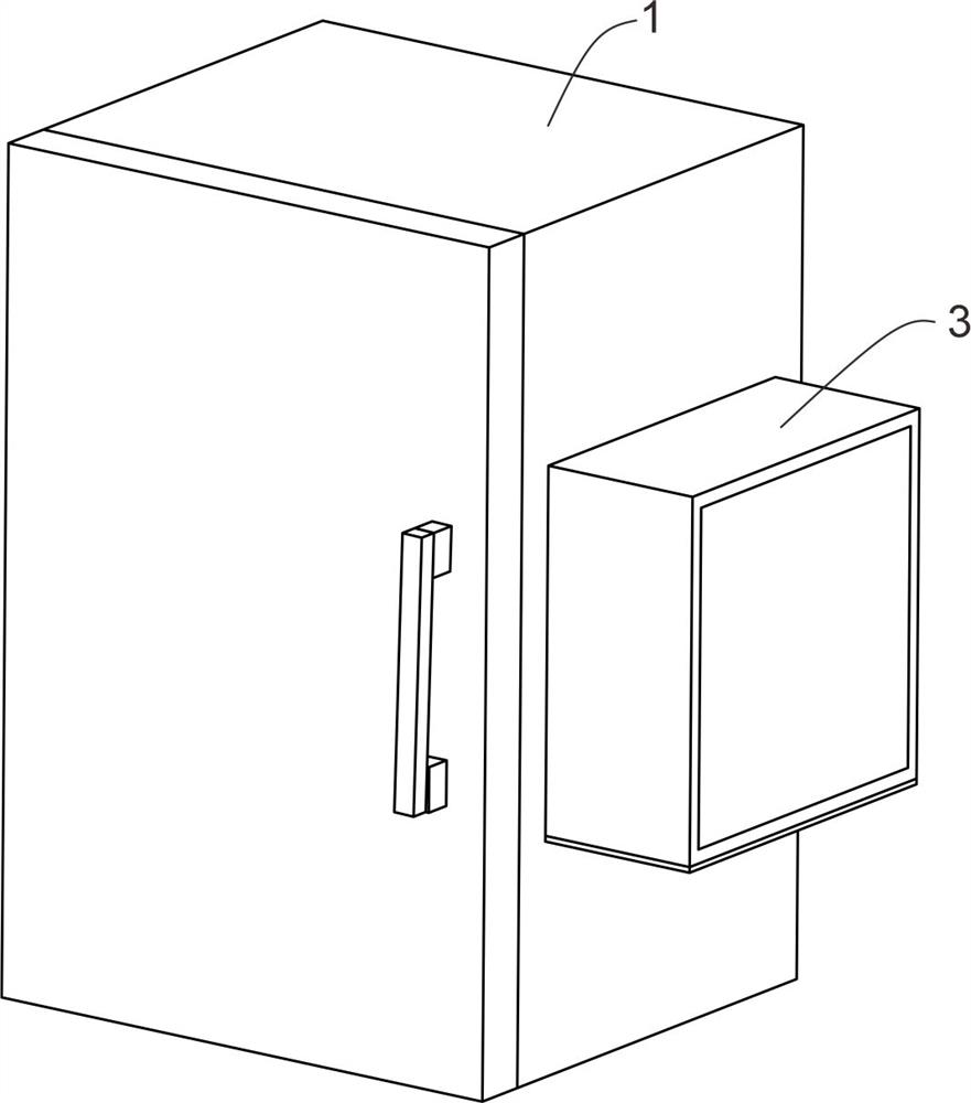
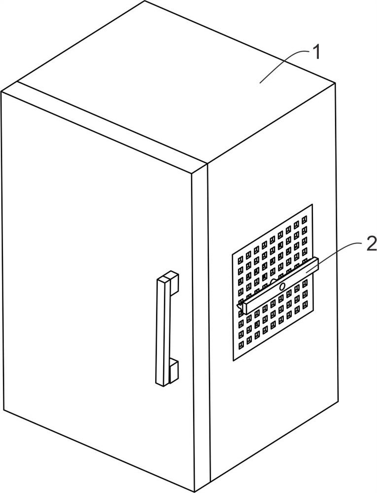
[0029] see Figure 1 to Figure 5 , the present invention provides a heat-resistant capacitor, including a casing 1 for protecting the capacitor; a dust-proof plate 11 for preventing dust from sticking to the fan blades 216; a heat dissipation unit 2 for discharging the heat inside the casing 1; The heat sink 21 for discharging the heat inside the casing 1; the cleaning member 22 for cleaning the surface of the dustproof plate 11; the protection unit for protecting the object (3) the air inlet 12 for easy entry of air; The exhaust port 13 for expelling heat; the through slot 14 for air flow; the wire hole 15 for easy installation of lead wires; the sliding door 16 for opening the casing 1;

[0030] Among them, the casing 1 for protecting the capacitor includes a dustproof plate 11 provided on both sides to prevent dust from sticking to the fan blades 216 ; a heat dissipation unit 2 for discharging the heat inside the casing 1 ; The cooling element 21 for discharging and the cl...

Embodiment 2

[0034] see Image 6 , the present invention provides a heat-resistant capacitor, which is used for installing the fixing seat 211 of the mounting seat 213; the bracket 212 for fixing the fixing seat 211; the mounting seat 213 for fixing the motor 214; A rotating motor 214 ; a mounting ring 215 that drives the fan blade 216 to rotate; a fan blade 216 that drives the air flow to discharge the hot air from the exhaust port 13 ; the first rotating rod 217 that drives the mounting ring 215 to rotate.

[0035] Further, the heat sink 21 includes a fixing seat 211 for installing the mounting seat 213 provided in the air outlet 13, and brackets 212 for fixing the fixing seat 211 are arranged around the fixing seat 211. The seat 211 is fixedly connected, and the other ends of the brackets 212 provided around are respectively fixedly connected to the inner wall of the air outlet 13 .

[0036]Further, the mounting seat 213 is fixedly connected with the fixing seat 211, the mounting seat ...

Embodiment 3

[0039] see Figure 7 , The present invention provides a heat-resistant capacitor, the second rotating rod 221 driving the fixed rod 222 to rotate; the fixed rod 222 driving the scraper 223 to rotate; the scraper 223 cleaning the surface of the dustproof plate 11 .

[0040] Further, the cleaning member 22 includes a second rotating rod 221 arranged on the other side of the mounting ring 215 and driving the fixing rod 222 to rotate. One end of the second rotating rod 221 is fixedly connected with the mounting ring 215, and the other end of the second rotating rod 221 penetrates through the mounting ring 215. The dust-proof plate 11 extends to the side of the dust-proof plate 11, and one end of the second rotating rod 221 extending to the side of the dust-proof plate 11 is provided with a fixed rod 222 that drives the scraper 223 to rotate. The fixed rod 222 and the second rotating rod 221 is fixedly connected, one side of the fixing rod 222 is symmetrically provided with a scrap...


PUM


Abstract

The invention relates to the technical field of capacitors, in particular to a heat-resistant capacitor which comprises a shell, a heat dissipation unit and a protection unit, the shell comprises dustproof plates arranged on the two sides, the heat dissipation unit comprises a heat dissipation piece for discharging heat in the shell and a cleaning piece for cleaning the surfaces of the dustproof plates, the heat dissipation piece is located in the shell, and the protection unit is located in the shell. The cleaning piece is located on one side of the dustproof plate, and the protection unit comprises a protection cover located on one side of the exterior of the shell. According to the invention, hot air absorbing heat in a through groove is discharged through rotation of fan blades, so that the interior of the shell is cooled, the temperature in the capacitor is rapidly discharged, and thus the usability of the capacitor is ensured, the fan blades drive a second rotating rod while discharging the hot air, so that the second rotating rod drives a fixed rod to rotate, and the heat dissipation efficiency of the capacitor is improved. And the fixed rod drives the scraper blade to clean the surface of the dustproof plate embedded in the inner wall of the air outlet, so that the heat dissipation effect is prevented from being reduced due to excessive dust accumulation, and the normal service life of the capacitor is ensured.

Description

technical field [0001] The invention relates to the technical field of capacitors, in particular to a heat-resistant capacitor. Background technique [0002] Capacitors are widely used electronic components. With the rapid development of electronic information technology, the replacement of digital electronic products is getting faster and faster, which drives the rapid development of the capacitor industry. When the existing capacitors are working, if the ambient temperature is too high. If it is too high, the heat generated by the capacitor itself cannot be dissipated through normal channels, which will reduce the insulation performance of the metallized polypropylene film, thereby reducing the withstand voltage capability. life. SUMMARY OF THE INVENTION [0003] The object of the present invention is to provide a heat-resistant capacitor to solve the above-mentioned problems in the background art. [0004] In order to achieve the above object, the present invention pr...

Claims


Application Information

Patent Timeline
IPC IPC(8): H01G2/08H01G2/10
CPCH01G2/08H01G2/10
Inventor 李成连
Owner 李成連
Learn More