
Cooling Storage Cabinet and Method of Operating Thereof

a technology of cooling storage cabinet and cooling chamber, which is applied in the direction of domestic cooling apparatus, static/dynamic balance measurement, instruments, etc., can solve the problems of refrigerating compartment cooling, and achieve the effect of preventing local overcooling, reducing cooling capacity, and reducing rotational speed of inverter compressor

Inactive Publication Date: 2009-09-24
HOSHIZAKI ELECTRIC CO LTD
View PDF5 Cites 23 Cited by
  • Summary
  • Abstract
  • Description
  • Claims
  • Application Information

AI Technical Summary

Benefits of technology

The present invention relates to a cooling storage cabinet with two storage compartments that can be individually cooled. The cabinet includes an inverter compressor, a condenser, a valve unit, constriction units, evaporators, and a refrigerant circulation path. The invention provides a method for controlling the compressor to supply refrigerant to the evaporators while changing the rotational speed of the inverter compressor based on the set temperatures of the storage compartments and the internal temperatures of the compartments. The method can also include decreasing the rotational speed of the inverter compressor when the internal temperature of one of the storage compartments becomes lower than the set temperature, stopping the inverter compressor when the internal temperature of both compartments become lower than the set temperature, and decreasing the rotational speed of the inverter compressor when the internal temperature of one of the storage compartments becomes higher than the set temperature. The invention also includes a compressor control means that can decrease the rotational speed of the inverter compressor in stages or at predetermined intervals to ensure proper cooling and motor oil circulation. The technical effects of the invention include efficient cooling of the storage compartments, improved control of the cooling process, and reduced risk of overcooling.

Problems solved by technology

However, because of such a higher rotational speed of the compressor, there is a concern of over cooling capacity, which results in over cooling of the refrigerating compartment.

Method used


Image

  • Cooling Storage Cabinet and Method of Operating Thereof
  • Cooling Storage Cabinet and Method of Operating Thereof
  • Cooling Storage Cabinet and Method of Operating Thereof

Examples


Embodiment Construction

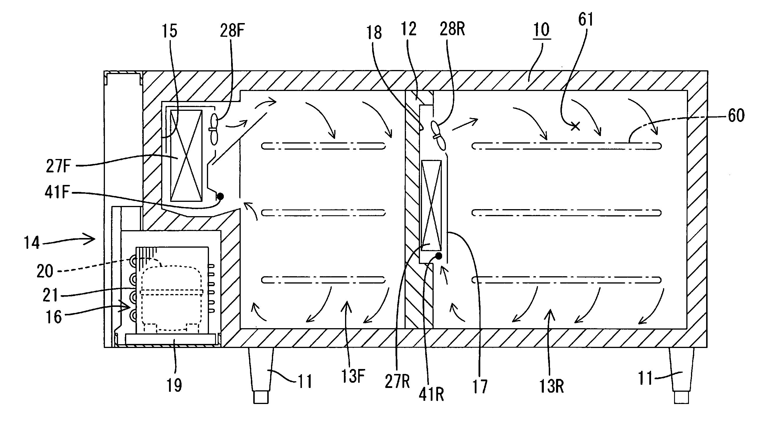
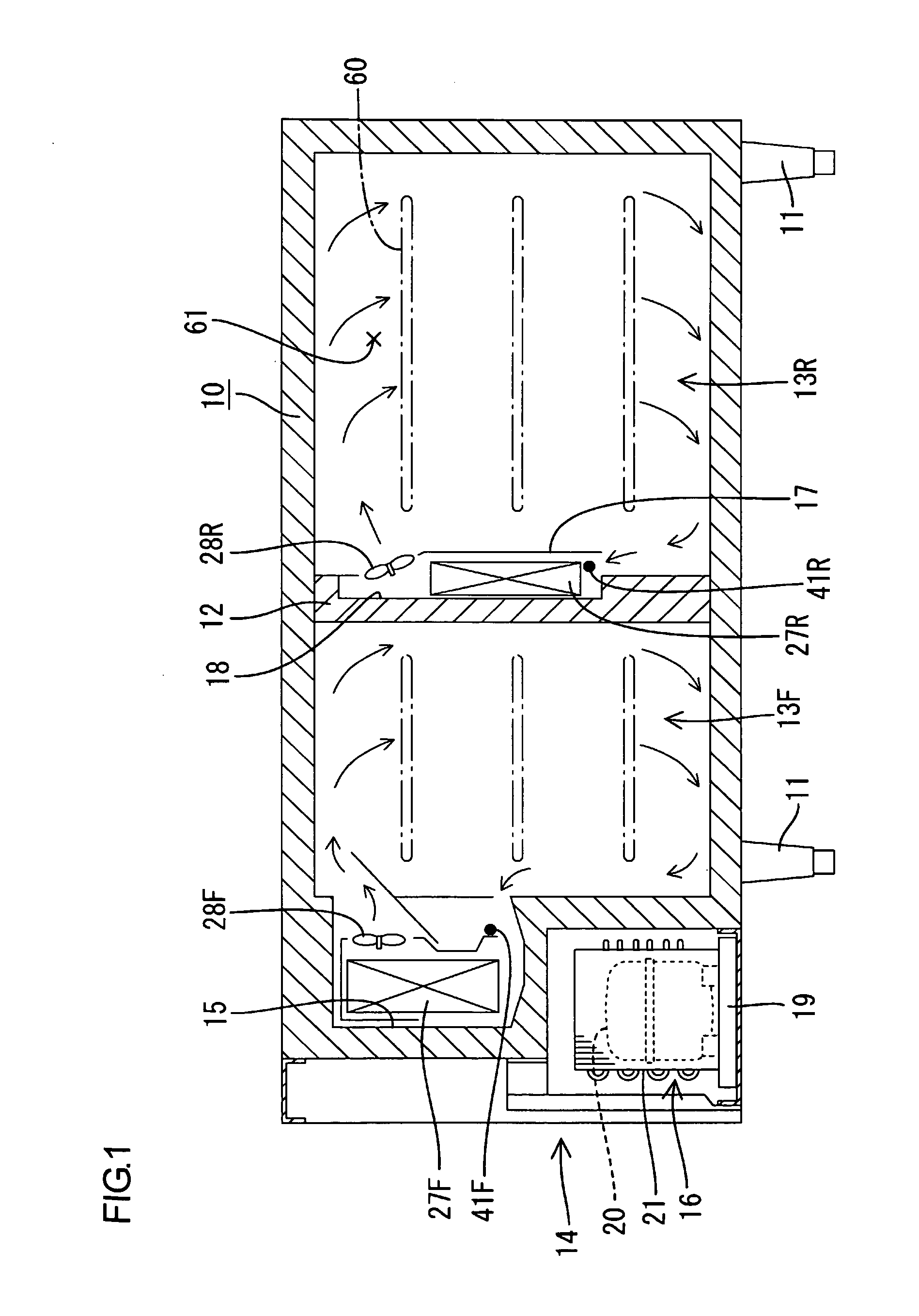
[0031]An embodiment in accordance with the present invention will hereinafter be explained with reference to FIGS. 1 through 11. Illustrated in this embodiment is a freezer-refrigerator of horizontal type (table type) for commercial use.

[0032]First, a general structure will be explained with reference to FIG. 1. Reference symbol 10 indicates a storage cabinet body, which is configured by a horizontally longer heat-insulating box body. The heat-insulating box body has an opening in front thereof. The storage cabinet body 10 is supported by legs 11. The legs 11 are provided in four corners on a bottom face of the storage cabinet body 10. The inside of the storage cabinet body 10 is separated into right and left sides by an additional heat-insulating partition wall 12. The left and relatively narrower side is defined as a freezing compartment 13F. The freezing compartment 13F corresponds to a first storage compartment. The right and wider side is defined as a refrigerating compartment ...


PUM


Abstract

When an internal temperature of a freezing compartment becomes lower than a lower limit temperature TF(OFF) during R-compartment F-compartment alternate cooling, a request for start of R-individual overcool preventing control is made. Then, the rotational speed of the compressor is decreased by one stage and, subsequently, a three-way valve comes to a “R-side open state”, and thus individual cooling of the refrigerating compartment is executed. Thereafter, after a set time, the rotational speed of the compressor is decreased by one stages. When the refrigerating compartment becomes lower than a lower limit temperature TR(OFF), a request for stop of the R-individual overcool preventing control is made. Then, the process shifts to individual cooling of the freezing compartment and then, after waiting for the freezing compartment to again become lower than the lower limit temperature, the compressor is stopped. When shifted to the individual cooling of the refrigerating compartment, the rotational speed of the compressor is drastically decreased in a short time, i.e. the cooling capacity is drastically decreased.

Description

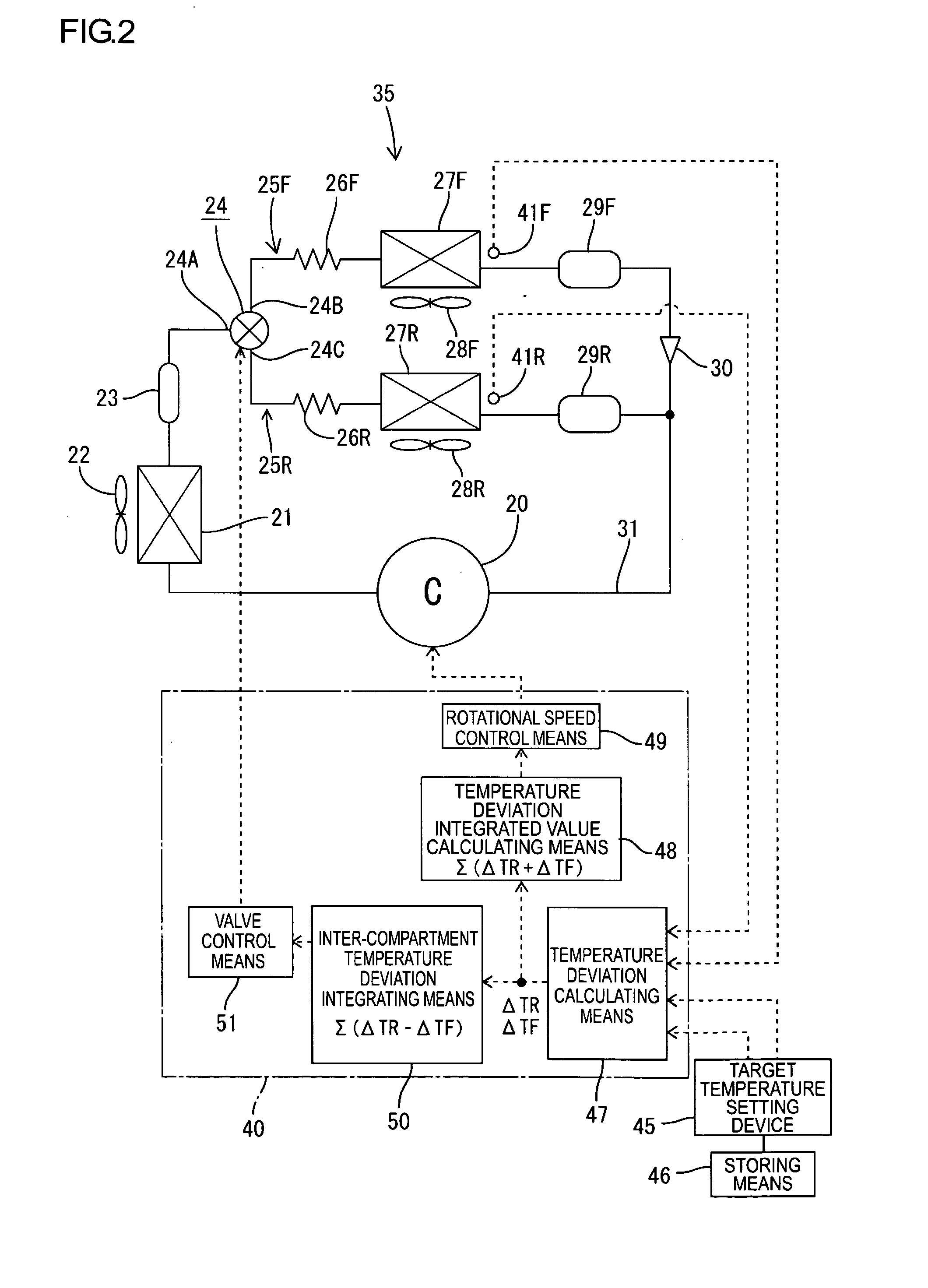
TECHNICAL FIELD[0001]The present invention is related to a cooling storage cabinet having a plurality of evaporators and supplying refrigerant from a single compressor to the evaporators, and a method of operating the same.BACKGROUND ART[0002]A known cooling storage cabinet is described in Patent Document 1. In this art, a freezing compartment and a refrigerating compartment are formed by separating the inside of a heat-insulating storage cabinet body. The freezing compartment and the refrigerating compartment each are heat insulated. The freezing compartment and the refrigerating compartment each have respective set temperatures differing from each other. Each of the compartments has an evaporator, and a single compressor supplies refrigerant alternately to evaporators to cool the compartments.[0003]More specifically, a cooling cycle is configured as follows. An inverter motor operates a compressor. An outlet side of the compressor is connected to a condenser. The downstream side o...

Claims


Application Information

Patent Timeline
Patent Type & Authority Applications(United States)
IPC IPC(8): F25B1/00F25D11/00G05B15/00
CPCF25B5/02F25B49/025F25B2600/021F25B2600/2511Y02B40/32F25D29/00F25D2700/10Y02B30/741F25D11/022Y02B30/70Y02B40/00F25B1/00F25D11/02
Inventor YANAGIDA, SHINYAKONDOU, NAOSHISUYAMA, AKIRA
Owner HOSHIZAKI ELECTRIC CO LTD
Learn More