
Special fixture for turning two end surfaces of thin-wall conical part

A special fixture and two-end technology, applied in metal processing mechanical parts, clamping, manufacturing tools, etc., can solve problems such as easy deformation, achieve the effect of short processing cycle, simple fixture structure, and overcome technical problems

Active Publication Date: 2014-12-31
HARBIN JIANCHENG GRP
View PDF6 Cites 0 Cited by
  • Summary
  • Abstract
  • Description
  • Claims
  • Application Information

AI Technical Summary

Problems solved by technology

[0003] The purpose of the present invention is to provide a special fixture for turning thin-walled conical parts on both ends to solve the problem that the thin-walled conical parts are easily deformed when clamping, and the shape of the thin-walled conical parts is conical and cannot be clamped by general-purpose fixtures. question

Method used


Image

  • Special fixture for turning two end surfaces of thin-wall conical part
  • Special fixture for turning two end surfaces of thin-wall conical part
  • Special fixture for turning two end surfaces of thin-wall conical part

Examples


specific Embodiment approach 1

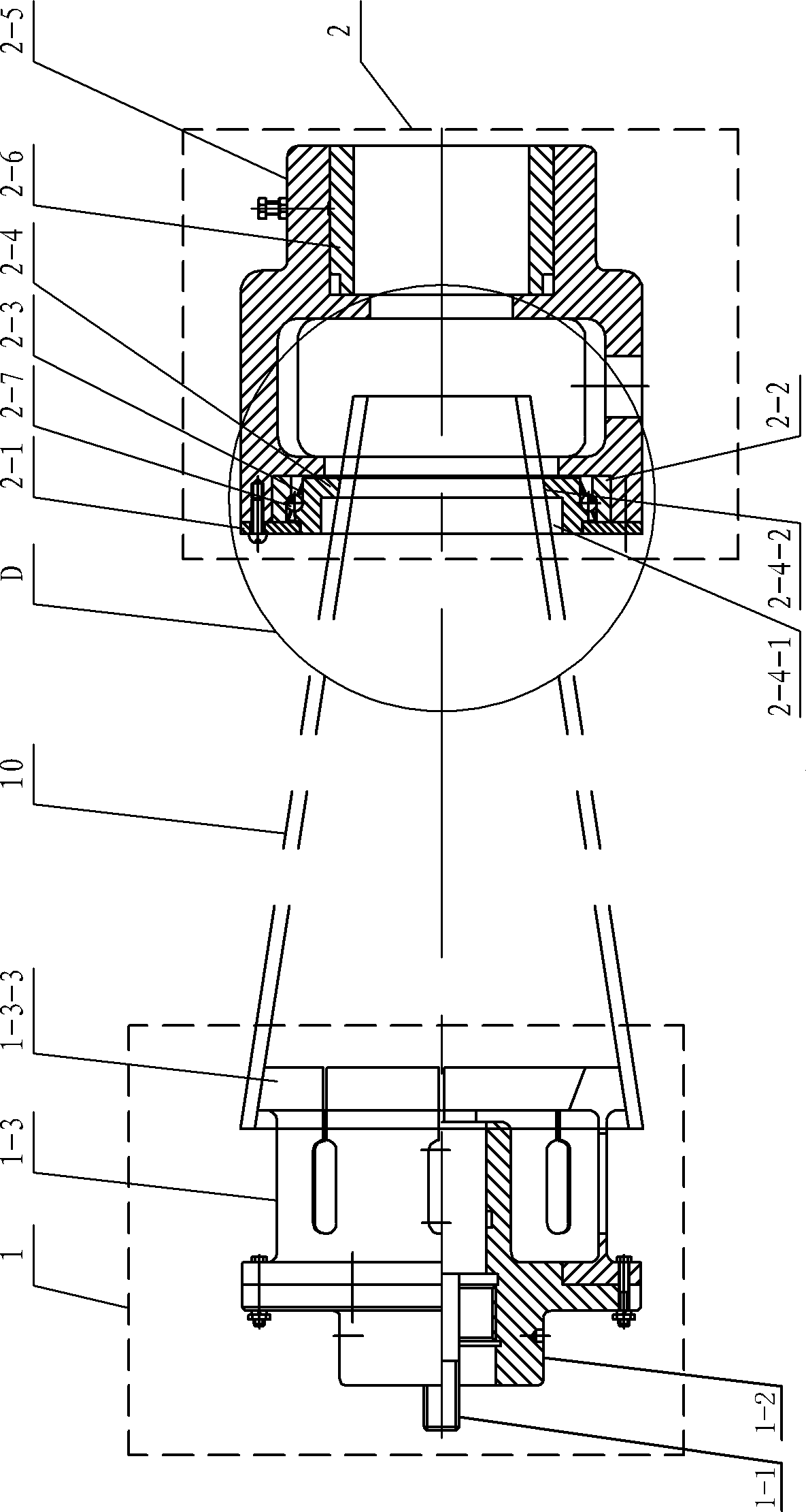
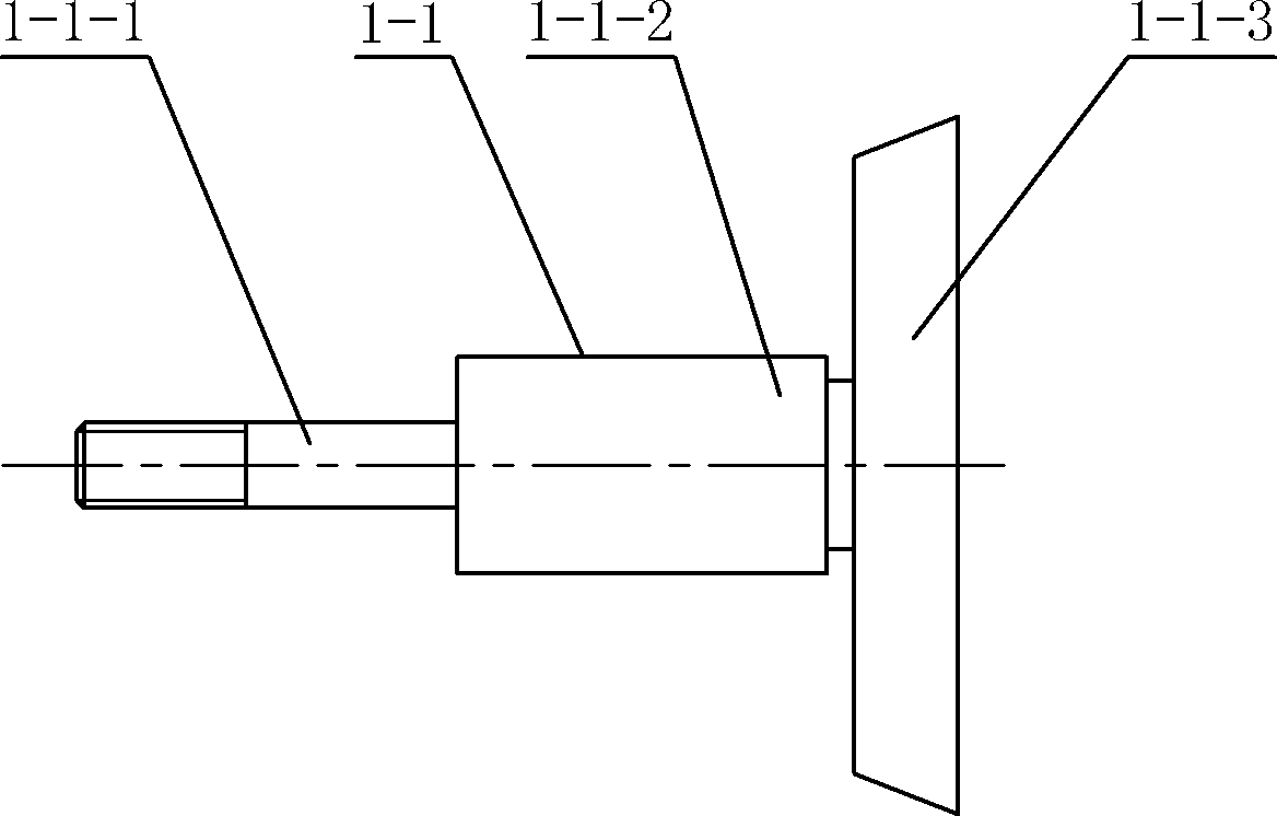
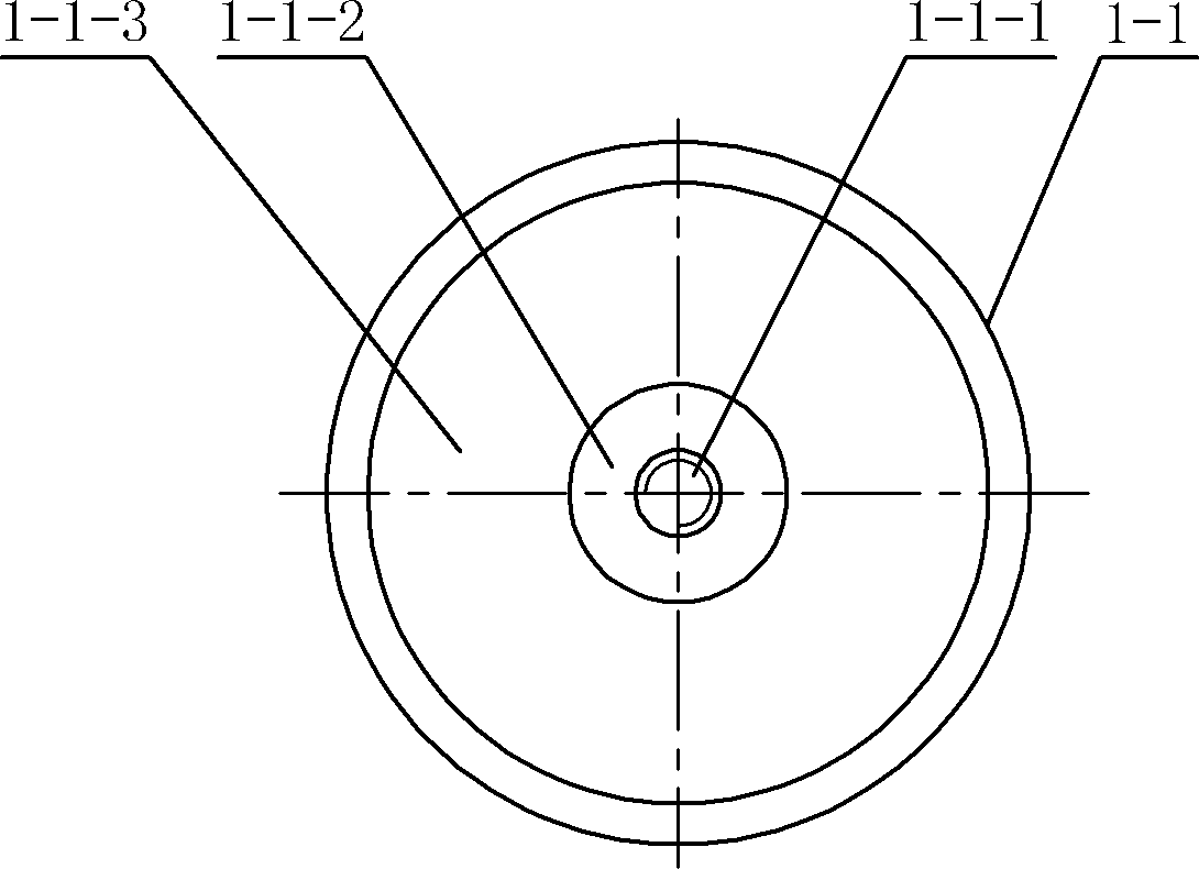
[0010] Specific implementation mode one: combine Figure 1 to Figure 13 Explain, the special fixture for the two ends of the turning thin-walled conical part of the present embodiment, the special fixture includes an elastic clamp 1 and an apical body 2, and the elastic clamp 1 and the apical body 2 are coaxially arranged; the elastic clamp 1 includes a mandrel 1 -1, the first clip body 1-2 and the elastic chuck 1-3; the tail top body 2 includes a baffle plate 2-1, an outer ring 2-2, a bead frame 2-3, an inner ring 2-4, and a second clip Concrete 2-5, bushing 2-6 and multiple balls 2-7;

[0011] The center of one side end face of the first clamping body 1-2 is provided with lathe spindle positioning hole 1-2-1 sequentially along the axial direction (to ensure that the axis of the first clamping body 1-2 is coaxial with the lathe spindle), the lathe spindle thread Connecting hole 1-2-2 (to ensure reliable connection between the special fixture and the lathe spindle, to prevent...

specific Embodiment approach 2

[0013] Specific implementation mode two: combination Figure 7 It is explained that eight axial long holes 1-3-2-1 are evenly distributed along the circumference of the tube wall of the thin-walled circular tube 1-3-2 in this embodiment. Others are the same as in the first embodiment.

specific Embodiment approach 3

[0014] Specific implementation mode three: combination Figure 6 and Figure 8 To illustrate, the slit width of the long slit 1-3-2-2 in this embodiment is 2-3mm. Others are the same as in the first embodiment.


PUM


Abstract

The invention relates to a special fixture for turning two end surfaces of a thin-wall conical part, aiming at solving the problems that the thin-wall conical part is apt to be deformed during clamping and cannot be clamped by using a universal fixture. The connecting shaft of a mandrel sequentially penetrates through the mandrel positioning hole of a first fixture body, a lathe main shaft threaded connecting hole and a lathe main shaft positioning hole and is arranged outside the first fixture body. The circular-truncated-cone-shaped shaft of the mandrel is arranged outside the first fixture body. An axial long hole and an axial long slit are arranged on the wall of the thin-wall round pipe of an elastic chuck. The circular-truncated-cone-shaped end of the elastic chuck is provided with an end conical hole. The elastic chuck is fixedly sheathed on the first fixture body. An inner ring and an outer ring are installed in the bearing shoulder hole of a tail ejection body. A ball retainer is installed between the inner ring and the outer ring. Balls are installed on the ball retainer. A turning hole and a chip hole are arranged in the wall of a connecting hole in the second fixture body of the tail ejection body. The special fixture is used for clamping and positioning during turning of the two end surfaces of the thin-wall conical part.

Description

technical field [0001] The invention relates to a fixture for turning both ends of thin-walled conical parts. Background technique [0002] Thin-walled conical parts are formed by coil welding of thin steel plates with a wall thickness of δ. The wall thickness δ of thin-walled conical parts is generally 1 to 5 mm, and the cone angle is α (see Figure 13 ), both ends need to be set to finished size. Since the thin-walled conical parts are easily deformed when clamping, and the shape of the thin-walled conical parts is conical, it cannot be clamped with a general-purpose fixture (three-jaw chuck or four-jaw chuck). Contents of the invention [0003] The purpose of the present invention is to provide a special fixture for both ends of turning thin-walled conical parts, so as to solve the problem that thin-walled conical parts are easily deformed when clamping, and the shape of thin-walled conical parts is conical and cannot be clamped by general-purpose fixtures. question. ...

Claims


Application Information

Patent Timeline
Patent Type & Authority Patents(China)
IPC IPC(8): B23Q3/12
Inventor 曾庆富武晓燕宋兴君于晶张洪涛
Owner HARBIN JIANCHENG GRP
Learn More