Carbonizing system and carbonizing process of wood materials
A technology of carbonization and raw materials, which is applied in the petroleum industry, biofuels, special forms of dry distillation, etc., can solve the problems of low heat transfer efficiency, slow cooling speed, and the difficulty of increasing the recovery of by-products of carbonization reaction, etc., so as to increase the heat transfer area and effectively Good for carbonization
- Summary
- Abstract
- Description
- Claims
- Application Information
AI Technical Summary
Problems solved by technology
Method used
Image
Examples
Embodiment 1
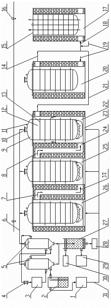
[0066] like figure 1 As shown, the carbonization system in this embodiment includes a carbonization device, a by-product recovery device and related auxiliary equipment (ie, the lifting device 16).
[0067] The above-mentioned carbonization device includes a reaction vessel and a reaction chamber for placing the reaction vessel;
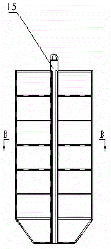
[0068] Wherein the reaction vessel includes a material rack 15 and a retort 12 for placing the material rack 15; the retort 12 is composed of a retort body (not shown in the figure) and a retort cover 9, and the retort cover 9 is provided with an exhaust port 10 and temperature measuring port 11;
[0069] The reaction chamber includes a calciner 26 with a combustion zone, a carbonization chamber 25, a preheating chamber 22 arranged in sequence, and a drying chamber 17 and a cooling chamber 20 for pretreatment and post-treatment of woody raw materials respectively, wherein the calciner 26 The exhaust port is connected with the air inlet of the carbo...
Embodiment 2
[0075] Compared with Example 1, the only difference is that in this embodiment, in the middle of the retort 12, 6 rods inserted from the bottom are evenly distributed, and turn horizontally near the top of the retort body and pass from the side of the retort body 2. An inverted L-shaped flue pipe passed through; the ratio of the total cross-sectional area of the flue pipe to the cross-sectional area of the retort 12 is 3 / 200.
Embodiment 3
[0077] Compared with Example 1, the difference is only that: in this embodiment, the outer fins 13 are spiral fins arranged on the outer wall of the retort, and the spiral fins form a circle around the inner walls of each reaction chamber. The internal flue of the retort body spiral. During the heat transfer process, the high-temperature flue gas rises along the spiral flue and exchanges heat with the retort.
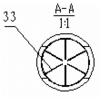
[0078] The inside of the retort 12 is centered on its central axis, and four rectangular inner fins 33 are evenly and symmetrically distributed across the middle, the adjacent angles are 90°, and the height is the same as that of the retort. The material rack 15 is provided with 4 layers of sub-supports, each layer of support is laid with grid nets, and each layer of grid nets has 4 openings that are at the same position as the inner fins 33 .
PUM
| Property | Measurement | Unit |
|---|---|---|
| angle | aaaaa | aaaaa |
| length | aaaaa | aaaaa |
| width | aaaaa | aaaaa |
Abstract
Description
Claims
Application Information
 - R&D
- Intellectual Property
- Life Sciences
- Materials
- Tech Scout
- Unparalleled Data Quality
- Higher Quality Content
- 60% Fewer Hallucinations
Browse by: Latest US Patents, China's latest patents, Technical Efficacy Thesaurus, Application Domain, Technology Topic, Popular Technical Reports.
© 2025 PatSnap. All rights reserved.Legal|Privacy policy|Modern Slavery Act Transparency Statement|Sitemap|About US| Contact US: help@patsnap.com


