Method for preparing buried medium antenna

A technology for buried antennas and antennas in a medium, applied in the structural form of radiating elements and other directions, can solve problems such as difficulty, low yield and low melting point, and achieve the effects of reducing volume, improving yield and stable performance.

Inactive Publication Date: 2012-12-05
中国人民解放军桂林空军学院
View PDF1 Cites 2 Cited by
  • Summary
  • Abstract
  • Description
  • Claims
  • Application Information

AI Technical Summary

Problems solved by technology

[0004] Although the research on dielectric-embedded antennas has been started, there is no relatively mature theory and technology to completely bury the antenna in the dielectric and process it into one with the dielectric, especially there is no complete and feasible preparation method, because the antenna and the dielectric are processed The integrated process is difficult and the yield is low, and the antenna is generally copper, which has a low melting point. In the selection of the medium, it must not affect the performance of the antenna, and it must be ensured that the copper sheet will not be melted and deformed during the sintering process. , so it is difficult

Method used


Image

  • Method for preparing buried medium antenna
  • Method for preparing buried medium antenna
  • Method for preparing buried medium antenna

Examples


preparation example Construction

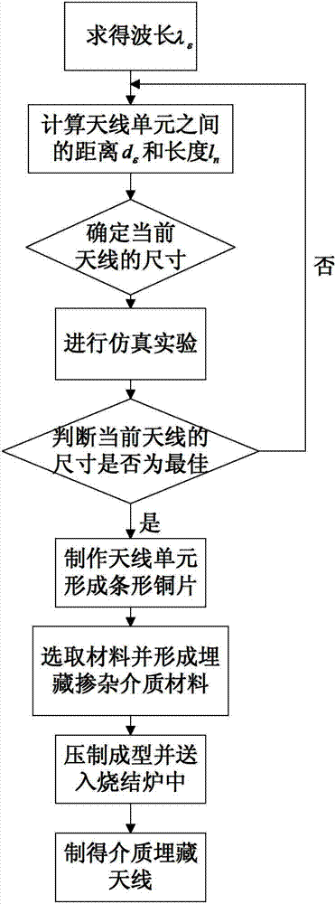
[0027] as attached figure 1 As shown, the present invention provides a method for preparing a dielectric buried antenna, the steps of which are as follows:

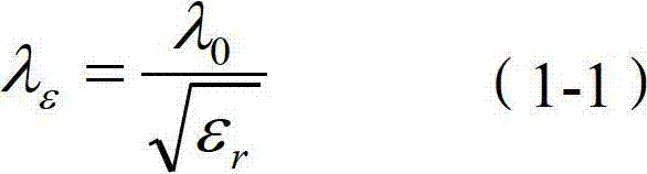
[0028] Step 1: Obtain the wavelength of the electromagnetic wave in the medium space according to the formula (1-1);

[0029] λ ϵ = λ 0 ϵ r - - - ( 1 - 1 )

[0030] Among them, λ 0 is the wavelength of the electromagnetic wave in free space (free space means the medium is air), λ ε is the wavelength of the electromagnetic wave in the medium space, ε r is the dielectric constant;

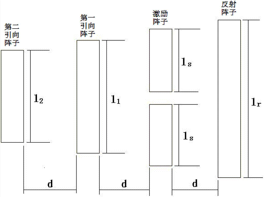
[0031] Step 2: The antenna is generally composed of several antenna units, and there is a certain distance between each antenna unit; according to the wavelength λ obtained in ...

Embodiment 1

[0047] Example 1: The mass ratio of the yttrium group rare earth to the barium bismuth oxide-based ceramic material is 1 / 1000, the temperature of the sintering furnace is controlled to 850° C. and after sintering for 3 hours, the temperature is artificially controlled and gradually cooled to obtain a dielectric buried antenna.

Embodiment 2

[0048] Example 2: The mass ratio of the yttrium group rare earth to the barium bismuth oxide-based ceramic material is 3 / 1000, the temperature of the sintering furnace is controlled at 860° C. and after sintering for 3.5 hours, the temperature is artificially controlled and gradually cooled to obtain a dielectric buried antenna.


PUM


Abstract

The invention provides a method for preparing a buried medium antenna, and belongs to the technical field of electromagnetic fields and microwaves. The preparation method comprises the following steps of: totally burying a self-designed copper antenna into a ceramic medium material doped with an yttrium group of rare earth formula to ensure that a metal part of the antenna is not exposed; forming and manufacturing the copper antenna; sintering the copper antenna at a specific temperature; and manually reducing the temperature of the sintered copper antenna to prepare the buried medium antenna of which the metal part of the antenna can be seamlessly integrated with a buried medium. By the ceramic medium, the antenna is subjected to the sintering and is buried into the ceramic medium, so that the antenna can be seamlessly integrated with the ceramic medium to guarantee stable performance; the metal part of the antenna is insusceptible to corrosion and environmental interference on the metal part is reduced; a bismuthic acid barium-based ceramic material is adopted to fill the antenna, and a melting point of the bismuthic acid barium-based ceramic material is lower than that of a copper sheet, so that melting and deformation of the copper sheet in the sintering process are avoided, and the design requirement of the buried medium antenna can be easily met; and therefore, the rate of finished products is improved.

Description

technical field [0001] The invention relates to a preparation method, in particular to a preparation method of a dielectric buried antenna, and belongs to the technical field of electromagnetic fields and microwaves. Background technique [0002] At present, antennas can be mainly divided into small electric antennas (such as vehicle-mounted AM vertical receiving antennas), resonant antennas (such as half-wave vibrator antennas), broadband antennas (such as helical antennas), and aperture antennas (such as horn antennas), etc. At present, these antennas These antennas are all exposed on the surface of the equipment. These antennas either cannot conform to the equipment when installed, or are subject to certain restrictions in mass production, or have high production costs, or the metal part of the antenna exposed to the air is oxidized and corroded. [0003] The dielectric buried antenna, as the name implies, is a type of antenna that buries the antenna in the dielectric. A...

Claims


Application Information

Patent Timeline
Patent Type & Authority Applications(China)
IPC IPC(8): H01Q1/36
Inventor 倪国旗骆颖
Owner 中国人民解放军桂林空军学院
Why Eureka
Try Eureka