Pile foundation soaking load test method based on creep-strain separation

A technology of load test and pile foundation, which is applied in the test of foundation structure, foundation structure engineering, construction, etc., and can solve the problems of large errors in the calculation results of the axial force of the pile body, etc.

Active Publication Date: 2012-12-05
CHINA JK INST OF ENG INVESTIGATION & DESIGN
View PDF4 Cites 9 Cited by
  • Summary
  • Abstract
  • Description
  • Claims
  • Application Information

AI Technical Summary

Problems solved by technology

[0008] In summary, since the pile foundation immersion load test takes a long time, under long-term loading, the concrete will not only undergo elastic strain, but also creep. However, in the previous test work, the influence of creep was ignored, and the Substituting the measured strain into the calculation formula of elastic theory to calculate the axial force of the pile body, the calculation result of the axial force of the pile body is bound to have a large error

Method used


Image

  • Pile foundation soaking load test method based on creep-strain separation
  • Pile foundation soaking load test method based on creep-strain separation
  • Pile foundation soaking load test method based on creep-strain separation

Examples


Embodiment 1

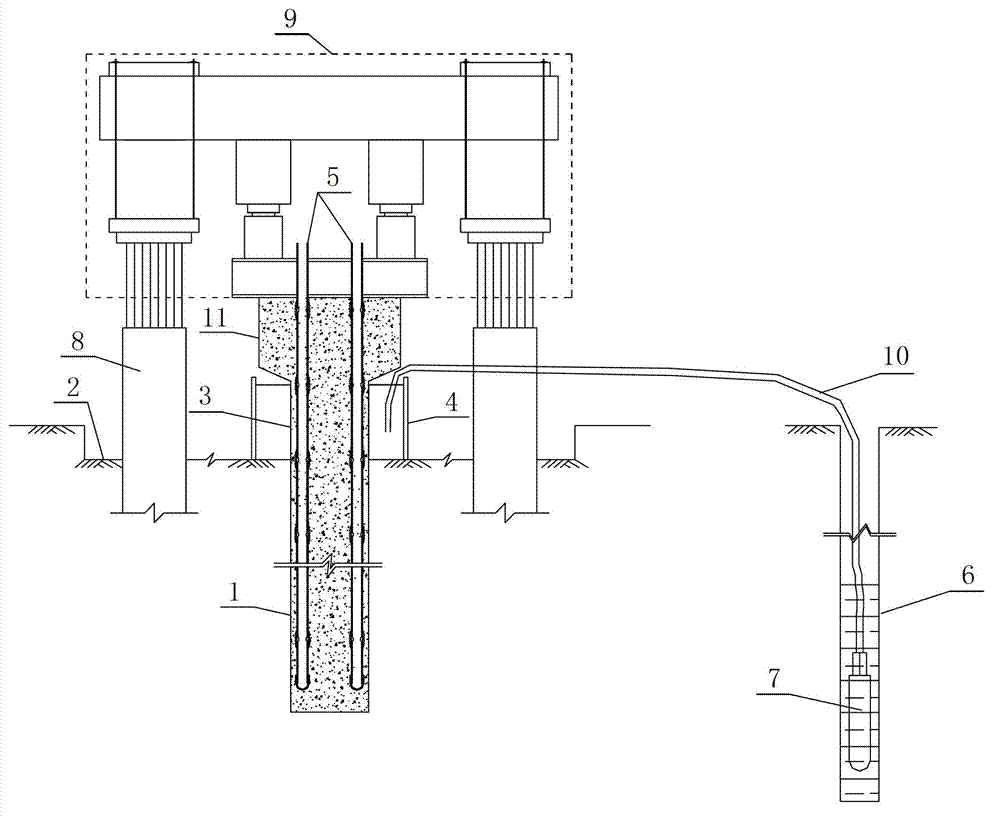
[0071] Such as figure 1 , figure 2 Shown, the pile foundation flooding load test method based on creep strain separation of the present invention, comprises the following steps:

[0072] Step 1. Constant load loading: Load the completed test pile 1 from top to bottom, and the load on the top of the test pile 1 is F N ; The stress applied on the top of the test pile 1 pile In the formula, A is the pile cross-sectional area of ​​test pile 1.

[0073] The test pile 1 is vertically arranged on a concrete pile in the collapsible loess stratum, and the test pile 1 has a pile head above the ground.

[0074] In this embodiment, the test pile 1 is a cylindrical pile, and the surrounding side of the test pile 1 is excavated to form a test pit 2 for the pile foundation immersion load test. The test pit 2 is a flat-bottomed pit, and the test pit 2 Mark one is flush with the pit bottom of the flat-bottomed pit. A water tank 4 is arranged on the outside of the calibration section 3 ,...

Embodiment 2

[0171] Such as Figure 4 As shown, in this embodiment, the difference from Embodiment 1 is that the test pile 1 described in step 1 is a prestressed pipe pile; A measuring pipe 5 is installed in the stress pipe pile, and the measuring pipe 5 is arranged vertically in the middle of the pipe pile core of the prestressed pipe pile; of the target. Moreover, the number of the measuring tube 5 is one. The cross section of the pile body of the prestressed pipe pile is circular, and because the bottom of the pile is closed, the cross section of the end of the prestressed pipe pile is circular.

[0172] After the installation of the measuring pipe 5 is completed, the filling material 12 is injected into the cavity between the pipe pile core of the prestressed pipe pile and the measuring pipe 5 from bottom to top using the grouting equipment, and the filling material 12 is It is a mixed slurry formed by uniform mixing of water, cement and bentonite according to the weight ratio of 10...


PUM

PropertyMeasurementUnit
Pile diameteraaaaaaaaaa
Pile lengthaaaaaaaaaa
Heightaaaaaaaaaa

Abstract

The invention discloses a pile foundation soaking load test method based on creep-strain separation, which comprises the steps as follows: firstly, a constant load is loaded; secondly, strain values of a pile body and internal force of the pile body before the soaking are tested, that is, when the settlement of a test pile is stabilized, the strain values in different depth positions of the pile body of the test pile are tested and the internal force in different depth positions of the pile body of the test pile before the soaking are analyzed; thirdly, the soaking is conducted and the strain values of the pile body during the soaking are tested, that is, when the settlement of the test pile is stabilized, the test pile is soaked, and after the test pile is soaked, the strain values in different depth positions of the pile body of the test pile are tested at regular intervals of Delta t; fourthly, an actually measured creep degree function of a calibration section is obtained; fifthly, the creep degree function during each loading age is obtained; and sixthly, the strain values of the pile body and the internal force of the pile body are calculated after creep separation during the soaking. The method disclosed by the invention has the advantages that the steps are simple, the testing is convenient, creep and strain can be separated from a pile body strain test result simply, conveniently, rapidly and accurately, so that the test result approximates to the practical stress state of the pile body as much as possible.

Description

technical field [0001] The invention relates to a pile foundation water immersion load test method, in particular to a pile foundation water immersion load test method based on creep strain separation. Background technique [0002] In the early 1980s, Professor K. Kovari of the Department of Rock and Tunnel Engineering at the Swiss Federal University of Technology Zurich proposed the principle of linewise observation, which is different from the principle of pointwise observation represented by strain gauges; and according to Based on the principle of line method monitoring, a series of portable instruments (including sliding micrometers) have been developed to distinguish them from fixed and buried instruments such as strain gauges and multi-point extensometers. Such instruments have applied for patents and entrusted Swiss Solexperts AG to produce them Sale. [0003] The sliding micrometer is a portable high-precision strain testing instrument developed according to the pr...

Claims


Application Information

Patent Timeline
IPC IPC(8): E02D33/00
Inventor 郑建国刘争宏张炜于永堂
Owner CHINA JK INST OF ENG INVESTIGATION & DESIGN
Why Eureka
Try Eureka