Electrode terminal of power module and welding method thereof

A technology of electrode terminals and power modules, applied in welding equipment, non-electric welding equipment, circuits, etc., can solve the problems of high-power modules, low welding efficiency, and difficult control of the welding surface, etc., and achieve the realization of ultrasonic welding process and welding Improved reliability and reduced welding fatigue

Active Publication Date: 2012-11-28
MACMIC SCIENCE & TECHNOLOGY CO LTD
View PDF6 Cites 6 Cited by
  • Summary
  • Abstract
  • Description
  • Claims
  • Application Information

AI Technical Summary

Problems solved by technology

However, this kind of electrode terminal structure can only release the stress in one direction, which cannot meet the needs of the increasingly developed high-power modules.
[0003] The electrode terminals on the existing power modules are all sintered on the metal layer of the metal-ceramic substrate by solder at high temperature, and the metal-ceramic substrate is directly bonded to aluminum oxide (AL2Q3) or aluminum nitride (Al2Q3) or aluminum nitride ( ALN) ceramic substrate surface, during the welding process, high temperature will cause welding stress on the solder layer between the metal layer of the metal-clad ceramic substrate and the electrode terminal, and the working environment of the power module is cycled at -40°C to 125°C , so after a period of time, it will eventually cause the connection between the metal layer of the cermet substrate and the electrode terminal to fall off, resulting in welding fatigue, which will affect the life of the overall power device
Secondly, the electrode terminals are welded on the metal layer of the cermet-clad substrate with solder, which not only has high requirements on the surface of the metal layer of the cermet-clad substrate and the surface of the electrode terminals, especially the gap between the copper foil of the cermet-clad substrate and the copper of the electrode terminal. There will also be a difference in thermal expansion, so its welding performance is not high, which affects its electrical conductivity
Furthermore, when the electrode terminals are sintered on the metal layer of the cermet-clad substrate by solder at high temperature, the welding process not only requires solder, flux and protective gas during welding, but also the high-temperature sintering and welding process takes a long time, especially the high temperature generated It is also easy to weaken the metal properties of other parts of the material. In addition, factors such as solder flow and solder mask ink during the welding process will also cause the risk of contamination on the welding surface. Because the welding surface is not easy to control, the process operation is complicated and the welding efficiency is low.

Method used


Image

  • Electrode terminal of power module and welding method thereof
  • Electrode terminal of power module and welding method thereof
  • Electrode terminal of power module and welding method thereof

Examples


Embodiment Construction

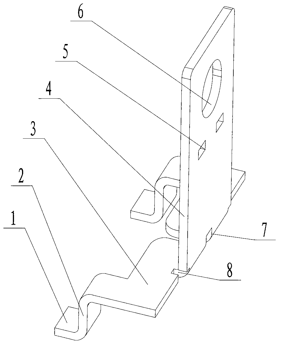
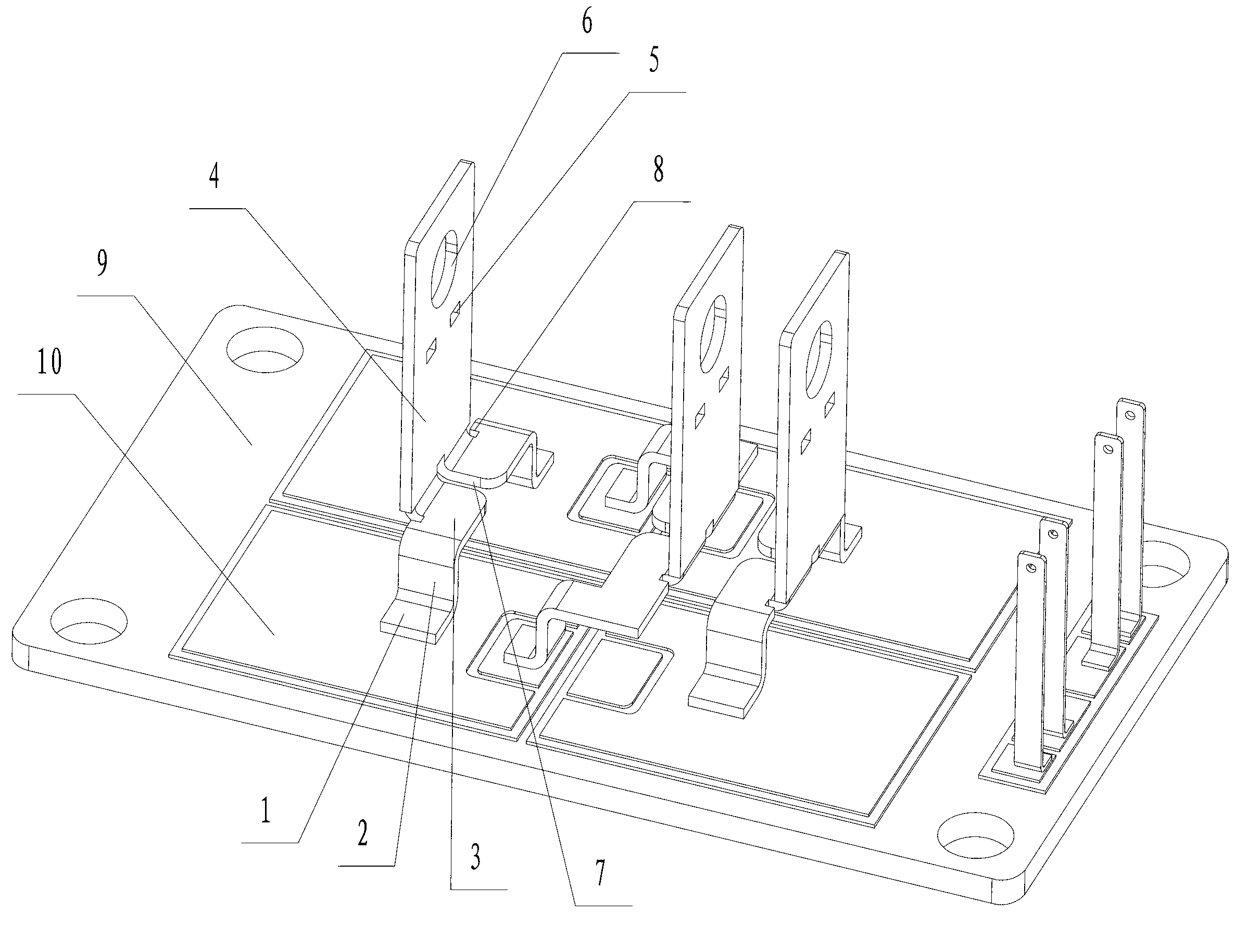
[0018] See figure 1 , 2 As shown, the power module electrode terminal of the present invention includes an integrated support and a lead-out plate 4, a through-hole 6 is provided on the lead-out plate 4, and at least one notch is provided at the bending part of the lead-out plate 4, which is convenient for the lead-out plate 4 bend, see image 3 , 4 As shown, the support of the electrode terminal of the present invention is pressure-welded on the metal layer of the metal-ceramic substrate 10, and the metal-ceramic substrate 10 is fixed on the bottom plate 9. The bottom plate 9 adopts a copper bottom plate and is connected with a heat sink, and the power module The heat during work is forcibly dissipated. The lead-out plate 4 of the electrode terminal of the present invention passes through the shell 11 and is bent and covered on the top of the shell 11, and is arranged on the electrode holder 11-1. The lead-out plate 4 is located at the bending part and has a At least one b...


PUM


Abstract

The invention relates to an electrode terminal of a power module. The electrode terminal comprises a support saddle and a run-off plate which are integrated, wherein a through hole is formed in the run-off plate; the support saddle comprises a transverse plate and upright plates, wherein the upright plates are arranged at two ends of two sides of the transverse plate and subject to arc curve transition, and moreover, connecting plates outwardly bent are arranged at the bottom of the upright plates; the bottom of the run-off plate is in curve transition to the transverse plate; an intermediate notch on the transverse plate extends to the curve transition part between the transverse plate and the run-off plate; and side notches are respectively arranged on two side surfaces of the curve transition part between the run-off plate and the transverse plate. The electronic terminal of the power module has a reasonable structure and can effectively release the stress caused by a welding part of the electronic terminal when being bent, prolong the service life and improve the welding efficiency.

Description

technical field [0001] The invention relates to a power module electrode terminal and a welding method thereof, belonging to the technical field of semiconductor power modules. Background technique [0002] The power module is mainly composed of a semiconductor chip such as an IGBT chip, a metal-clad ceramic substrate (DBC), a copper base plate, a casing, and input / output electrode terminals and signal terminals. Each electrode terminal is fixed on the metal layer of the metal-ceramic substrate by welding. , the other end of each electrode terminal goes out of the shell and is bent and set on the upper part of the shell, and then connected to the external power supply and the output working power supply through the fastener installation. At present, the electrode terminals of power modules are mostly composed of a groove part and a lead-out part. The groove part is a vertical groove structure, and the bottom is bent inward and welded on the metal layer of the metal-ceramic s...

Claims


Application Information

Patent Timeline
Patent Type & Authority Applications(China)
IPC IPC(8): H01M2/30B23K20/10
CPCY02E60/12Y02E60/10
Inventor 张敏麻长胜郑军姚玉双王晓宝
Owner MACMIC SCIENCE & TECHNOLOGY CO LTD
Why Eureka
Try Eureka