Eureka AIR delivers breakthrough ideas for toughest innovation challenges, trusted by R&D personnel around the world.

LED (Light-Emitting Diode) tube and manufacturing method thereof

A technology for LED fluorescent lamps and LED chips, which is applied to cooling/heating devices, lighting and heating equipment, point light sources, etc. and other problems to achieve the effect of improving system reliability and improving system repair ability.

Active Publication Date: 2014-11-05
中山芯蕊光电科技有限公司
View PDF7 Cites 0 Cited by
  • Summary
  • Abstract
  • Description
  • Claims
  • Application Information

AI Technical Summary

Problems solved by technology

The first method has limited improvement in heat dissipation, especially for fluorescent tubes with a closed inner cavity, reducing the ambient temperature of the closed cavity on the light-emitting side becomes the main contradiction. The second method increases the power consumption of LED fluorescent tubes and the manufacturing cost In addition, the possibility of failure in use increases. Although the third method solves the heat dissipation problem well and makes the temperature field in the entire airtight tube uniform, but due to the structural characteristics of the existing PCB board, the LED is used as the light output end of the luminous body. The opposite surface cannot be processed into a highly reflective surface, so the light output efficiency is reduced by 20% to 30%

Method used


Image

  • LED (Light-Emitting Diode) tube and manufacturing method thereof
  • LED (Light-Emitting Diode) tube and manufacturing method thereof

Examples


Embodiment 1

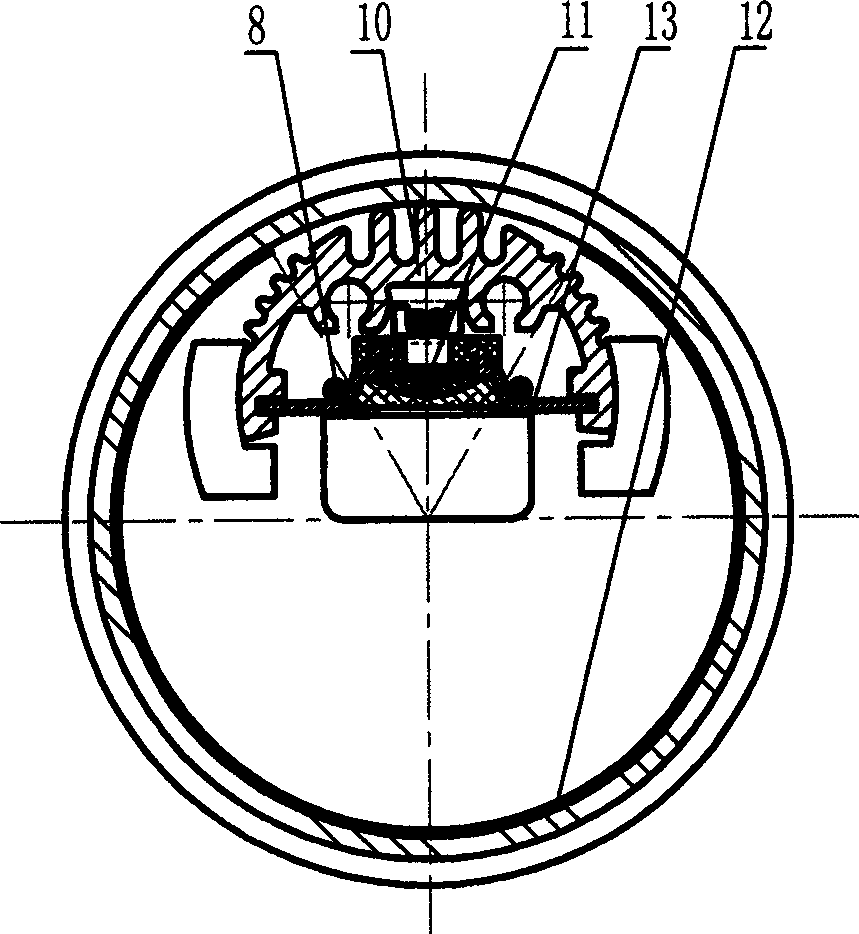
[0031] Embodiment one: if figure 1 , 2 As shown, an LED lamp tube includes: a steel conductive connection for completing the LED fluorescent lamp tube and the lamp holder, and an external copper column connected to the mains to connect the plastic end cover 1; an aluminum shell cover 2; Front power rectification and PFC value compensation module 3; plastic connection sleeve 4; self-adaptive apron pad 5; outer cover transparent glass tube 6; cantilever carrier and plastic connection sleeve 4 of rear drive chip and filter capacitor module 7 and outer cover transparent glass tube 6 axial support components. Front power rectification and PFC value compensation module 3; separate power rectification and PFC value compensation module assembly. The plastic connection sleeve 4 is a support member for the cantilever beam of the parallel circuit bearing panel of the LED chip 11 and the end face of the self-adaptive rubber ring pad 5 . The self-adaptive apron pad 5; self-adaptive to t...

Embodiment 2

[0032] Embodiment two: If the carrier of the mirror surface good heat conductor plate of the LED chip 11 module is housed in embodiment one is preferably a mirror surface aluminum plate, then the rapid absorption of the chip heat and the formation of the external heat transfer volume are greatly reduced. cost. If the cross-section of the diffuser film 12 with light-scattering function formed in an arc shape along the length direction of the inner tube wall of the lamp tube in the first embodiment is infiltrated with a red light-filling transparent pigment, the color rendering of the light of the LED lamp tube can be improved.


PUM


Abstract

The invention discloses an LED (Light-Emitting Diode) fluorescent tube. The LED fluorescent tube is provided with diffusion films which are arranged along the length direction of the inner tube wall of the tube in an arc shape and have a light equalizing and diffusion function; the bracket part of the tube is provided with a rubber ring pad with adaptive glass tube wall thickness and pipe diameter change; a power supply part is a function module combined switch power supply consisting of a power supply front rectifying and PFC (Power Factor Correction) value compensation module and a rear drive chip and filtering capacitor module separately arranged at the two ends of the tube; the outer cover of the tube is a transparent glass tube; the load bearing part of the LED chip is a mirror-surface good heat conductor plate; since the heat conduction and transfer aluminum section is bonded with the glass cover, the heat is quickly transferred to the outer surface of the glass cover and uniformly dissipated along the circumferential direction in a sealing cavity at the same time; and red fill-in light transparent pigment penetrates into the section of the diffusion film to form red fill-in light, and the color rendering of the light of the LED fluorescent tube is improved.

Description

technical field [0001] The invention relates to an LED lamp tube with an LED as a luminous body, in particular to a fluorescent lamp tube with a COMMB-LED integrated surface light source as a luminous body. Background technique [0002] Existing LED lamp tubes mostly use LEDs with independent beads as the illuminant, paste them on the PCB board with solder paste, and then attach them to the heat-dissipating and heat-transfer aluminum profiles. The aluminum profiles used as the outer cover are seamless with the PC cover. Fastening production, although the temperature of the aluminum profile is only about 55°C when the fluorescent tube of the LED as the illuminant is turned on, in order to achieve the purpose of eliminating string light and uniform light, a PC cover mixed with diffusing powder is installed on the light-emitting surface, but due to The poor heat transfer ability of the PC cover makes the temperature of the closed space formed by the LED as the illuminant and th...

Claims


Application Information

Patent Timeline
Patent Type & Authority Patents(China)
IPC IPC(8): F21S2/00F21V29/00F21V5/08F21V9/10F21V23/00F21Y101/02F21V9/40F21V29/503F21V29/89
Inventor 彭雯
Owner 中山芯蕊光电科技有限公司
Why Eureka
Eureka Blog
Learn More