
Method for controlling steel slab gap in heating furnace

A heating furnace and gap technology, applied in the direction of heat treatment furnace, heat treatment process control, furnace, etc., can solve the problems of non-dynamic adjustment, inability to dynamically adjust the loading stroke, increase the difficulty of heating control of wide and thick slabs, etc., to reduce stickiness The frequency of uneven heating of steel and slabs, the effect of reducing quality defects and improving production efficiency

Active Publication Date: 2012-10-24
BAOSHAN IRON & STEEL CO LTD
View PDF4 Cites 28 Cited by
  • Summary
  • Abstract
  • Description
  • Claims
  • Application Information

AI Technical Summary

Problems solved by technology

Generally, the design and control of the slab gap in the heating furnace of the thick plate factory is based on the general design of hot rolling heating furnaces at home and abroad: all the slab gaps in the furnace are fixed values ​​(a value after the on-site debugging is completed after the process requirements ), cannot be dynamically adjusted during production, which makes it impossible to dynamically adjust the loading stroke calculation and vacancy calculation in the PLC automation control layer according to the different slab specifications
The fixed and non-adjustable slab gap also makes it impossible for the process control computer system to realize the dynamic tracking of the slab in the heating furnace according to the different slab specifications
However, there are many types of slabs for thick plates, which are quite different from hot rolling, which increases the difficulty of heating control of slabs with different width and thickness specifications in the furnace, and cannot ensure uniform and thorough burning of wide and thick slabs, which is prone to steel sticking and slab heating uniformity, directly affect the surface quality of the finished steel plate

Method used


Image

  • Method for controlling steel slab gap in heating furnace
  • Method for controlling steel slab gap in heating furnace
  • Method for controlling steel slab gap in heating furnace

Examples


Embodiment

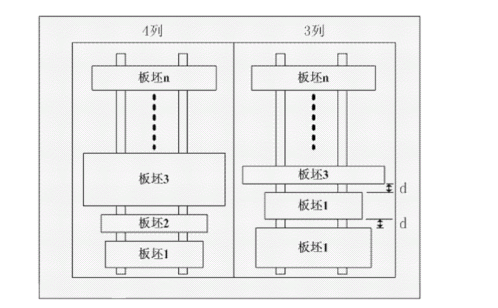
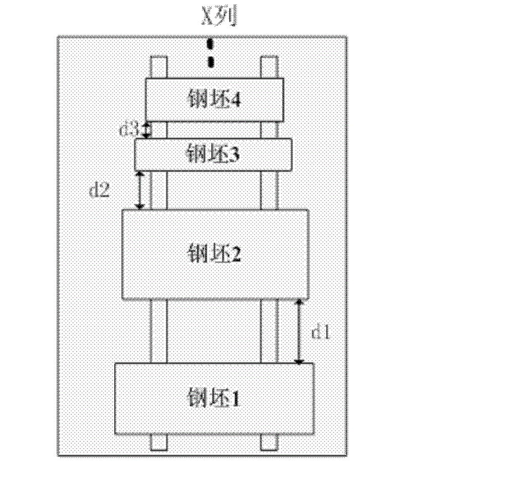
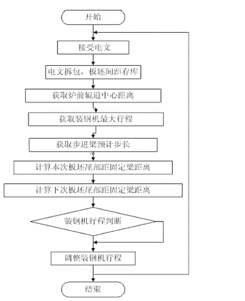
[0063] The invention relates to a method for controlling the billet gap in a heating furnace. The method comprises the control of the steel loading stroke, the control of the steel loading vacancy and the position tracking of the furnace map. The action flow of steel loading is as follows: the steel loading machine is responsible for sending steel billets of different specifications into the heating furnace for heating. First, the arm of the loading machine pushes the slab to be positioned in front of the furnace, then backs up, lifts up the slab, advances it to the target position, and returns to the original position after falling, that is, a steel loading task is completed. The calculated value of the loaded steel stroke is determined by installing an incremental pulse encoder at the end of the shaft of the variable frequency motor, and then connecting it to the counting module of the on-site signal acquisition station through a shielded cable to complete signal processing. ...


PUM


Abstract

The invention relates to a method for controlling the steel slab gap in a heating furnace. The method comprises the steps of steel stroke control, steel vacancy control and furnace map position track, wherein a formula that A=A1+A2-A3-A4 is adopted in the steel vacancy control step; A is a distance from a next steel slab to the tail of a fixed beam, and is in mm; A1 is a distance between the last slab on the fixed beam and the tail of the fixed beam, and is in mm; A2 is a step pitch of a stepping beam, and is in mm; A3 is a slab gap and is in mm; and A4 is a slab width. The slab spacing in the slag heating furnace is dynamically adjusted and tracked through the steel stroke control, the steel vacancy control and the furnace map position track according to the method for controlling the steel slab gap in the heating furnace of the invention, so slab surface quality defects caused by the slab gap are reduced. The heating non-uniformity generation frequency of bonding steel and the slabs is substantially reduced, the slab heating quality is ensured, and the production efficiency is improved.

Description

technical field [0001] The invention relates to a control method and belongs to the field of automatic control. Specifically, it is a method for controlling the gap between steel slabs in a heating furnace to reduce quality defects on the surface of slabs. Background technique [0002] There are many reasons for the surface defects of thick plate products, such as the uniformity of slab heating temperature, the number of slabs in the furnace per unit time, and the time of slabs in the furnace. Among them, the size of the gap between the slabs in the furnace directly affects various performance indicators of the slab heating. If the gap between slabs is too large, the number of slabs passing through the heating furnace per unit time will decrease, and the heat energy of the heating furnace will not be fully utilized, resulting in energy loss; if the gap between slabs is too small, it will easily cause the slabs to stick to steel and cause slide rails during the furnace contr...

Claims


Application Information

Patent Timeline
IPC IPC(8): C21D11/00C21D9/70C21D9/46
Inventor 王红施珂鲁岩汪鎏李开杰戎戈
Owner BAOSHAN IRON & STEEL CO LTD
Learn More