
Gasoline engine cooling system

A cooling system, gasoline engine technology, applied in the direction of engine cooling, liquid cooling, coolant flow control, etc., can solve the problem of engine emissions and fuel economy deterioration, reduced cooling system cooling performance, engine outlet water temperature response lag, etc. problems, to achieve the effect of reducing fuel consumption and emissions, improving cooling performance, and reducing the frequency of opening

Active Publication Date: 2012-10-03
ANHUI JIANGHUAI AUTOMOBILE GRP CORP LTD
View PDF5 Cites 8 Cited by
  • Summary
  • Abstract
  • Description
  • Claims
  • Application Information

AI Technical Summary

Problems solved by technology

However, in such a cooling system, when the cylinder block and the cylinder head are cooled, part of the cooling water is evaporated, and the generated air bubbles are transferred to the water pump, and as a result, air suction occurs in the water pump, thereby apt to lower the cooling system. cooling performance
At the same time, the thermostat is arranged at the water inlet of the water pump, and the response to the engine outlet water temperature is relatively lagging, and because the coolant from the heater and throttle directly returns to the water pump, the coolant cannot stay around the temperature-sensing element of the thermostat. The thermostat cannot be fully preheated, the main valve of the thermostat cannot be opened in time, the large cycle cannot be opened in time, and the engine is prone to overheating
In addition, during the engine warm-up process of this cooling system, the main valve of the thermostat is frequently opened and closed, which is likely to cause abnormal fluctuations in engine temperature, prolong the engine warm-up time, and cause engine emissions and fuel economy to deteriorate; Thermal shock in the cooling system reduces the service life of related components

Method used


Image

  • Gasoline engine cooling system
  • Gasoline engine cooling system
  • Gasoline engine cooling system

Examples


Embodiment

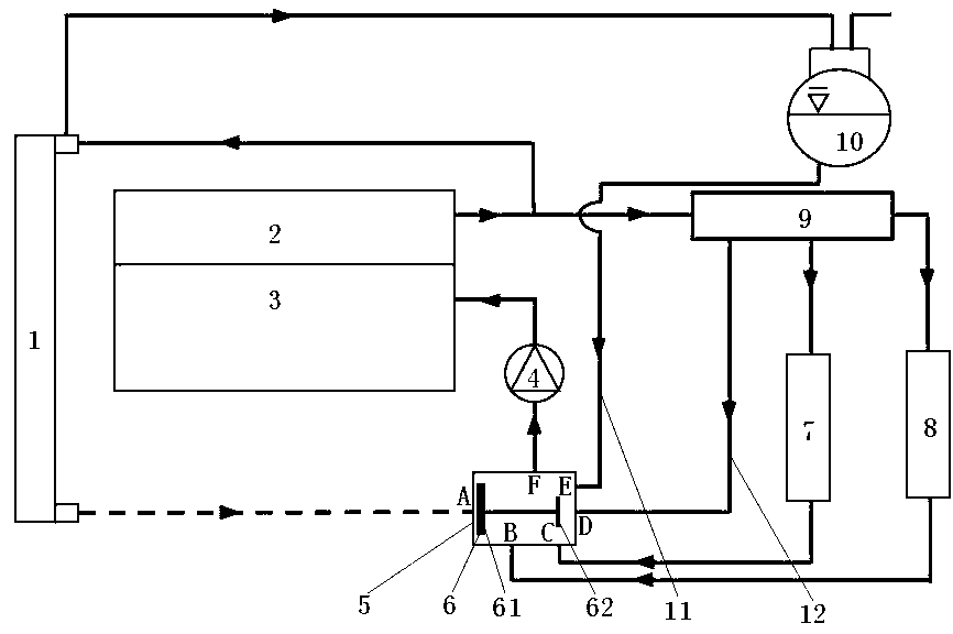
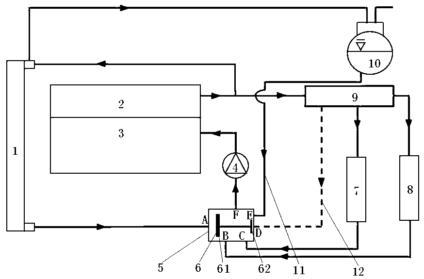
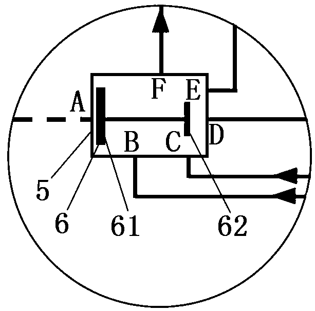
[0018] see figure 1 , a gasoline engine cooling system includes a radiator 1, a cylinder head water jacket 2, a cylinder block water jacket 3, a water pump 4 and an expansion tank 10. The upper water chamber of the radiator 1 is connected to the water inlet of the expansion tank 10, and the water outlet of the cylinder head water jacket 2 is respectively connected to the upper water chamber of the radiator 1 and the water inlet of the water distribution pipe 9 through a three-way pipe. The second outlet and the first outlet of the valve are respectively connected to the inlet of the throttle valve 7 and the inlet of the heater 8; the water outlet of the cylinder block water jacket 3 is connected to the water inlet of the cylinder head water jacket 2; the water outlet of the water pump 4 is connected to the cylinder The water inlet of body water jacket 3. see image 3 , a thermostat 6 is installed inside the thermostat valve seat 5, and there are five inlets and one outlet F...


PUM


Abstract

The invention discloses a gasoline engine cooling system, which comprises a radiator, a cylinder cover water jacket, a cylinder body water jacket, a water pump, an expansion tank and a thermoregulator valve seat, wherein a thermoregulator is arranged in the thermoregulator valve seat; the thermoregulator valve seat is provided with five inlets and one outlet F; the first inlet A is communicated with a lower water chamber of the radiator; the second inlet B is communicated with the outlet of a fan heater; the third inlet C is communicated with the outlet of an air damper; the fourth inlet D is communicated with the outlet of a distributive pipe via a small circulation circuit; the fifth inlet E is communicated with the expansion tank via a water replenishing circuit; the outlet F is communicated with the water inlet of the water pump; the thermoregulator is a double-valve wax type thermoregulator and comprises a main valve and an auxiliary valve, wherein the main valve is installed on the first inlet A of the thermoregulator valve seat; and the auxiliary valve is just against the fourth inlet D of the thermoregulator valve seat. According to the gasoline engine cooling system disclosed by the invention, gas in cooling liquid can be removed to protect the water pump from cavitation, the cooling performance of the cooling system is improved, an engine is prevented from overheating, and thermal shock is prevented from generating in the cooling system.

Description

technical field [0001] The invention relates to an engine cooling system, in particular to a closed forced water cooling gasoline engine cooling system. Background technique [0002] In the existing gasoline engine cooling system, the coolant is generally directly pumped into the cylinder body through the water pump, enters the cylinder head from the water hole of the cylinder gasket, and then comes out from the cylinder head, and after being cooled by the radiator, it is cooled by the water pump through the water inlet. The controller returns to the water pump to form a large cycle, or directly returns to the water pump through the heater and throttle to form a small cycle; the thermostat is a single-valve wax type thermostat, which is usually arranged at the water inlet of the water pump. The specific principle is as follows: Figure 4 shown. However, in such a cooling system, when the cylinder block and the cylinder head are cooled, part of the cooling water is evaporated...

Claims


Application Information

Patent Timeline
IPC IPC(8): F01P3/18F01P5/10F01P7/16
Inventor 张建操杨林强张应兵姚伟陈园明苏晓芳
Owner ANHUI JIANGHUAI AUTOMOBILE GRP CORP LTD
Learn More