Conductive glass for thin film solar cell and preparation method thereof

A technology of solar cells and conductive glass, which is applied in the field of solar energy materials and photoelectric new materials, can solve the problem that the light transmission, conductivity and scattering degree of conductive glass have not been greatly improved, solar energy cannot be fully utilized and converted, and the increase of metal Problems such as the number of oxide conductive layers, etc., to achieve the effect of rich film structure, good anti-reflection effect, and good anti-reflection effect

Active Publication Date: 2016-03-30
CHANGZHOU ALMADEN
View PDF6 Cites 0 Cited by
  • Summary
  • Abstract
  • Description
  • Claims
  • Application Information

AI Technical Summary

Problems solved by technology

Therefore, in order to improve the light transmittance, etc., people continue to improve the structure of the transparent conductive film that affects the light transmittance, conductivity and scattering of conductive glass and increase the anti-reflection film. The setting of the anti-reflection layer is very important for improving the performance of conductive glass It has a certain effect, increasing the number of layers of the metal oxide conductive layer, changing one metal oxide conductive layer to multiple layers, but the multi-layer metal oxide conductive layers are still physically superimposed, and the transparent conductive film has a single layer structure , poor stability, these improved transparent conductive film layer structure does not substantially change the performance of conductive glass, and the light transmittance, conductivity and scattering degree of conductive glass have not been greatly improved
As a result, very huge solar energy cannot be fully utilized and converted, which reduces the conversion efficiency of solar energy and increases the cost of use

Method used


Image

  • Conductive glass for thin film solar cell and preparation method thereof

Examples


Embodiment 1

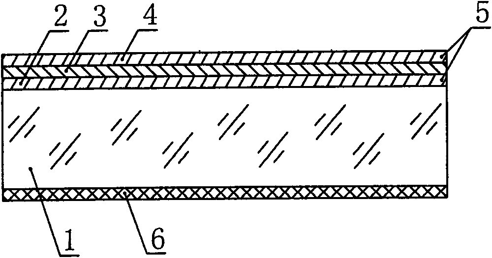
[0029] As shown in the drawings, a conductive glass for thin-film solar cells includes a glass substrate 1 , a transparent conductive film 5 , and an anti-reflection film 6 . The transparent conductive film 5 includes a metal oxide conductive layer 2 and a second metal oxide conductive layer 4, and a metal layer 3 is interposed between the metal oxide conductive layer 2 and the second metal oxide conductive layer 4, and the metal oxide The conductive layer 2 , the metal layer 3 and the second metal oxide conductive layer 4 are sequentially deposited on one side surface of the glass substrate 1 , and the antireflection film 6 is arranged on the other side surface of the glass substrate 1 . The glass substrate 1 is common float white glass with a thickness of 3.2 mm. The thickness of the metal oxide conductive layer 2 is 250nm, the thickness of the metal layer 3 is 50nm, the thickness of the second metal oxide conductive layer 4 is 250nm, the film thickness of the antireflection...

Embodiment 2

[0039] As shown in the accompanying drawings, a conductive glass for thin film solar cells, the structure of the conductive glass of this embodiment is basically the same as that of the first embodiment, the metal oxide conductive layer 2 is AZO, the metal layer 3 is a silver film, and the second metal The oxide conductive layer 4 is SnO 2 :F. The difference from Example 1 is: the glass substrate 1 is ultra-clear float glass with a thickness of 3.2mm; the thickness of the metal oxide conductive layer 2 is 150nm, the thickness of the metal layer 3 is 30nm, and the second metal oxide The thickness of the conductive layer 4 is 250nm, the thickness of the anti-reflection film 6 is 80nm, and the refractive index of the anti-reflection film is 1.22-1.4.

[0040] A preparation method for realizing the above-mentioned conductive glass for thin-film solar cells, the preparation method is basically the same as the preparation method in Example 1. the difference is:

[0041] The first...

Embodiment 3

[0049] As shown in the accompanying drawings, a conductive glass for thin film solar cells, the structure of the conductive glass of this embodiment is basically the same as that of the first embodiment, the metal layer 3 is a silver film, and the second metal oxide conductive layer 4 is SnO 2 :F. The difference from Example 1 is that the thickness of the metal oxide conductive layer 2 is 200nm, the thickness of the metal layer 3 is 50nm, the thickness of the second metal oxide conductive layer 4 is 300nm, and the film thickness of the antireflection film 6 is 120nm , the refractive index value of the anti-reflection film is 1.22-1.4. The metal oxide conductive layer 2 is GZO.

[0050] A preparation method for realizing the above-mentioned conductive glass for thin-film solar cells, the preparation method is basically the same as the preparation method in Example 1. the difference is:

[0051] The first step is identical with embodiment one;

[0052] In the second step, th...


PUM

PropertyMeasurementUnit
thicknessaaaaaaaaaa
thicknessaaaaaaaaaa
thicknessaaaaaaaaaa

Abstract

The invention particularly relates to conductive glass for a thin film solar battery and a preparation method of the conductive glass. According to the conductive glass provided by the invention, a metal layer (3) is clamped between a metallic oxide conductive layer (2) and a second metallic oxide conductive layer (4); and the metallic oxide conductive layer (2), the metal layer (3) and the second metallic oxide conductive layer (4) are sequentially arranged on one side surface of a glass base material (1); and an anti-reflective film (6) is arranged on the other side surface of the glass base material (1). The metallic oxide conductive layer is prepared on the glass base material through methods such as LPCVD (low pressure chemical vapor deposition), PECVD (plasma enhanced chemical vapor deposition), SPUTFER (magnetron sputtering) or SPRAY (hot spraying) method; the metal layer is prepared by a magnetron sputtering or thermal evaporation method; the second metallic oxide conductive layer is prepared by a chemical vapor deposition method; and the anti-reflective film is prepared by a sol-gel method. The conductive glass provided by the invention has the advantages of good light transmission, strong conduction, high scattering degree, good film layer structure stability, high cost performance and low preparation cost.

Description

technical field [0001] The invention relates to a new type of high-performance conductive glass, in particular to a conductive glass for a thin-film solar cell with a single-sided anti-reflection film on the opposite side and a preparation method thereof, which belongs to the field of photoelectric new materials, and is especially suitable for the field of solar materials. Background technique [0002] With the utilization of solar energy, which is a green, environmentally friendly and energy-saving new energy source, the development and development of new solar cells has increasingly become an important topic in the field of solar energy applications. At present, thin-film solar cells are widely used in solar cells. The quality of conductive glass as an important part of thin-film solar cells is directly related to the quality of thin-film solar cells. Therefore, the improvement and innovation of conductive glass for thin-film solar cells has always been very important. imp...

Claims


Application Information

Patent Timeline
Patent Type & Authority Patents(China)
IPC IPC(8): H01L31/0224H01L31/0216H01L31/18C03C17/245C03C17/36
Inventor 林金锡林金汉林于庭林鹏
Owner CHANGZHOU ALMADEN
Why Eureka
Try Eureka