
Plastic anchor floater

An anchor float and plastic technology, which is used in special purpose ships, ships, buoys, etc., can solve the problems of steel anchor float, easy corrosion of steel plates, large size, etc., to improve impact resistance, prolong service life, and float. good performance

Inactive Publication Date: 2012-09-19
中国水利水电第十三工程局有限公司橡塑制品厂
View PDF5 Cites 0 Cited by
  • Summary
  • Abstract
  • Description
  • Claims
  • Application Information

AI Technical Summary

Problems solved by technology

[0003] The purpose of the present invention is to provide a plastic anchor float to solve the problem of high anti-corrosion and maintenance requirements for anchor floats in the prior art, easy corrosion of steel plates, poor impact resistance, relatively short service life, and steel anchor floats themselves are heavy and bulky And other issues

Method used


Image

  • Plastic anchor floater
  • Plastic anchor floater

Examples


Embodiment Construction

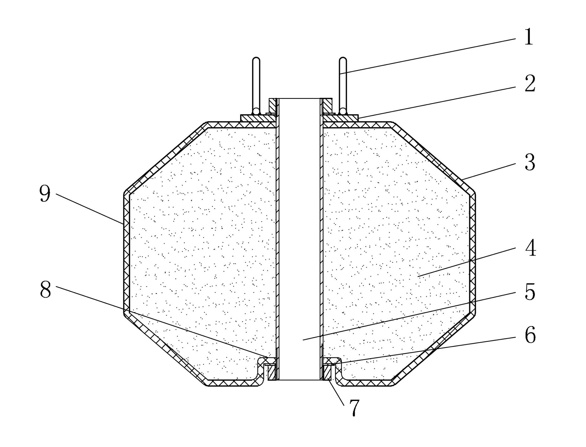
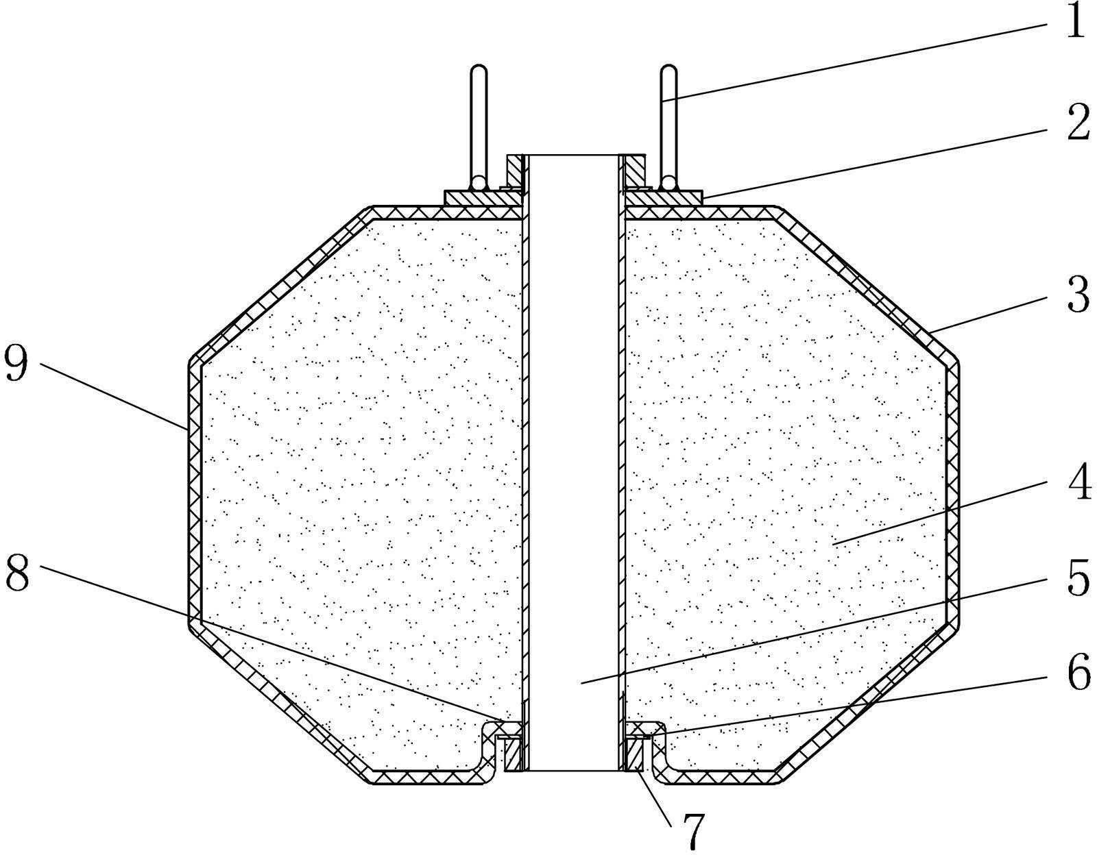
[0009] As shown in the figure: Change the steel shell of the anchor float 8 to a plastic shell 3, the shell 3 is equipped with a foam 4, the foam 4 is foam plastic, a steel pipe 5 is set in the center of the anchor float 8, and the steel pipe 5 uses a nut 7 , The flat pad 6 is connected to the clamping board 8 at the bottom of the anchor float 8. The clamping board 8 has a corner structure. A gland 2 is arranged on the top of the anchor drift 8, and two lifting rings 1 are arranged on the gland 2.


PUM


Abstract

The invention relates to a plastic anchor floater and belongs to the technical field of machinery manufacturing. A steel shell of the anchor floater is changed into a plastic shell; a foaming body is arranged in the shell; a steel pipe is arranged in the center of the anchor floater; the steel pipe is connected with a clamping plate at the bottom of the anchor floater through a nut and a flat cushion; a gland is arranged at the top of the anchor floater; and a plurality of lifting rings are arranged on the gland. The plastic anchor floater improves impact resistance and corrosion resistance, prolongs the service life and has light weight and high floating performance.

Description

Technical field [0001] The invention belongs to the technical field of mechanical manufacturing. Background technique [0002] Most of the existing anchor floats are welded by steel plates, which require high anti-corrosion maintenance. Because the tube steel plates are easily corroded, the impact resistance is poor, and the service life is relatively short. In addition, the steel anchor floats are heavy and bulky. Summary of the invention [0003] The purpose of the present invention is to provide a plastic anchor float, to solve the prior art anchor float high anti-corrosion maintenance requirements, the steel plate is easy to rust, impact resistance is poor, the service life is relatively short, in addition, the steel anchor float itself is heavy and bulky And other issues. [0004] The present invention is mainly composed of an anchor float main body and a lifting ring. The technical solution adopted to solve the problem is to change the anchor float steel shell to a plastic sh...

Claims


Application Information

Patent Timeline
IPC IPC(8): B63B22/00
Inventor 王春明蓝恭琰龚兴坤李新健陶冶
Owner 中国水利水电第十三工程局有限公司橡塑制品厂
Learn More