
Light-emitting diode (LED) anti-explosion lamp

A technology of explosion-proof lamps and lenses, which is applied to lighting devices, cooling/heating devices of lighting devices, light sources, etc., can solve the problems of complex structure of heat dissipation system, small cross-sectional area of ​​heat transfer base, and insufficient heat transfer efficiency, so as to improve heat transfer Thermal efficiency, simple and compact overall structure, and low manufacturing cost

Inactive Publication Date: 2012-08-08
UNIV OF SHANGHAI FOR SCI & TECH
View PDF15 Cites 2 Cited by
  • Summary
  • Abstract
  • Description
  • Claims
  • Application Information

AI Technical Summary

Problems solved by technology

The structure of the heat dissipation system in the above scheme is relatively complicated, because the contact area between the heat pipe or the heat sink and the shell is small, resulting in a large thermal resistance, which affects the overall heat dissipation effect
In the schemes disclosed in Chinese patents CN 201661872U and CN 201443739U, the LED is installed on the base integrated with the shell. Since the distance between the heat source and the outer surface of the shell is long, and the cross-sectional area of ​​the heat transfer base is small, the heat transfer efficiency still not high enough

Method used


Image

  • Light-emitting diode (LED) anti-explosion lamp
  • Light-emitting diode (LED) anti-explosion lamp
  • Light-emitting diode (LED) anti-explosion lamp

Examples


Embodiment Construction

[0023] The present invention will be further described below in conjunction with the accompanying drawings and embodiments.

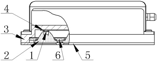
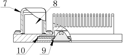
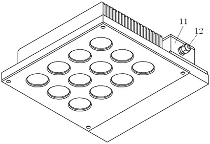
[0024] as attached Figure 1 to Figure 3 As shown, the LED explosion-proof lamp of the present invention is composed of LED1, lens 2, radiator 3, aluminum-based circuit board 4, cover plate 5, support plate 6, drive circuit 8 and its protective shell 7 and other components.

[0025] The LED light source is sensitive to temperature, and reasonable heat dissipation measures should be taken to keep the junction temperature of the LED within the rated range during normal operation. In an explosive environment, the LED1 and its driving circuit 8 are installed in a sealed protective casing 7 , and the heat generated by the LED1 needs to be dissipated to the external environment through the protective casing 7 . The present invention adopts the heat sink 3 in the form of a heat sink, utilizes the characteristics of the small size of the LED, and uses the heat...


PUM


Abstract

The invention relates to a light-emitting diode (LED) anti-explosion lamp. The LED anti-explosion lamp comprises LEDs, lenses, a radiator, an aluminum-based circuit board, a cover board, a supporting board, a protective shell, a driving circuit and an electric appliance box, wherein a plurality of high-power LEDs are arranged on the aluminum-based circuit board; the aluminum-based circuit board is arranged on the lower surface of the radiator; one lens is arranged on each high-power LED; and the lens is fixedly connected with the radiator through the supporting board and the cover board. The LED anti-explosion lamp adopts the radiating fin type radiator and utilizes the characteristic that the LEDs have small sizes, and the radiator serves as a constituent part of the protective shell, so the whole structure is simple and compact, the manufacturing cost is low, and the volume and the weight of the lamp are reduced. The LEDs are directly arranged below the radiating fins, so the heat conduction distance is short, the sectional area is large, and the heat transfer efficiency is improved. The strength of the glass lens is improved through toughening treatment; the additional protective shell is not required; the light distribution requirement in various occasions is met; and the lamp structure is simplified.

Description

technical field [0001] The invention relates to a lamp with LED as a light source, in particular to an increased safety LED explosion-proof lamp. Background technique [0002] Explosion-proof lamps are special lamps used in explosive environments. Various specific measures taken for electrical equipment to prevent ignition of the surrounding explosive environment are called explosion-proof types, including flameproof enclosure protection, increased safety protection and intrinsic safety protection, etc. (see Chinese National Standard GB836.1-2010). Among them, the safety-increased protection takes additional measures to prevent the possibility of dangerous temperatures, arcs and sparks under normal operation or specified abnormal conditions. [0003] LED is a solid-state light source, which uses DC power supply and has the advantages of high luminous efficiency, long life and small size. With the reduction of LED manufacturing cost, LED has been gradually used in explosion-...

Claims


Application Information

Patent Timeline
Patent Type & Authority Applications(China)
IPC IPC(8): F21S2/00F21V29/00F21V25/12F21Y101/02F21K9/232F21K9/235F21K9/238F21K9/69F21V29/76F21Y105/16F21Y115/10
Inventor 施伟斌翁振克苏胜君乐燕芬
Owner UNIV OF SHANGHAI FOR SCI & TECH
Learn More