
Silicon electrode plate for plasma etching

A plasma and silicon electrode technology, applied in the direction of circuits, discharge tubes, electrical components, etc., can solve problems such as difficulty in suppressing in-plane deviation of specific resistance value, difficulty in uniform etching speed, difficulty in suppressing in-plane deviation, etc., to achieve the realization of in-plane Internal uniformity, suppression of cracks or notches, and suppression of internal strain

Inactive Publication Date: 2012-08-01
MITSUBISHI MATERIALS CORP
View PDF1 Cites 1 Cited by
  • Summary
  • Abstract
  • Description
  • Claims
  • Application Information

AI Technical Summary

Problems solved by technology

Therefore, in order to suppress the unevenness of the surface, it is necessary to suppress the in-plane variation of the specific resistance value, but it is difficult to suppress the in-plane variation of the specific resistance value due to the in-plane variation of the dopant content.
Especially when the specific resistance value is high, the in-plane variation of the dopant content has a large influence, so it is difficult to suppress the in-plane variation of the specific resistance value
In this way, conventionally, it has been difficult to uniformly maintain the plasma density with the object to be etched, so there has been a problem that it is difficult to uniformize the etching rate in the wafer surface as the object to be etched.

Method used


Image

  • Silicon electrode plate for plasma etching
  • Silicon electrode plate for plasma etching
  • Silicon electrode plate for plasma etching

Examples


Embodiment

[0032] Next, the evaluation results of Examples of the silicon electrode plate produced according to the present embodiment described above will be described.

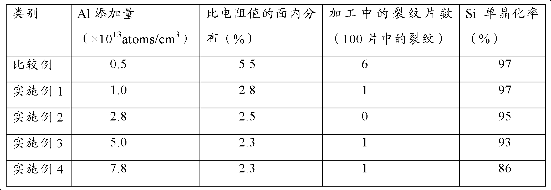
[0033] As shown in Table 1, the embodiment of the silicon electrode plate of the present invention is made by changing the addition amount of Al, and the in-plane distribution of the resistance value, the number of cracks in processing (the number of cracks in 100 pieces) and the number of Si single plates are compared respectively. The crystallization rate was investigated. These results are shown in Table 1. And, as a comparative example, it is also made to add less than 1×10 13 atoms / cm 3 The Al silicon electrode plate was evaluated in the same manner, and the results are also shown in Table 1. In addition, in any of the Examples and Comparative Examples, the amount of B added was set to 2×10 14atoms / cm 3 .

[0034] [Table 1]

[0035]

[0036] As judged from the evaluation results, the values ​​of the in-p...


PUM

PropertyMeasurementUnit
diameteraaaaaaaaaa

Abstract

To provide a silicon electrode plate for plasma etching that suppresses the unevenness of the surface caused by plasma etching so as to ensure uniform etching. [Means for Solving the Problems] The silicon electrode plate for plasma etching is constituted by single-crystal silicon in which B and Al have been added as dopants, wherein the concentration of Al is equal to or greater than 11013 atoms / cm3. In the silicon electrode plate for plasma etching, the electrical characteristic of single-crystal silicon is made uniform in a plane. Thus, the occurrence of unevenness of the surface may be minimized when the surface is depleted during plasma etching, and the occurrence of cracks may be suppressed.

Description

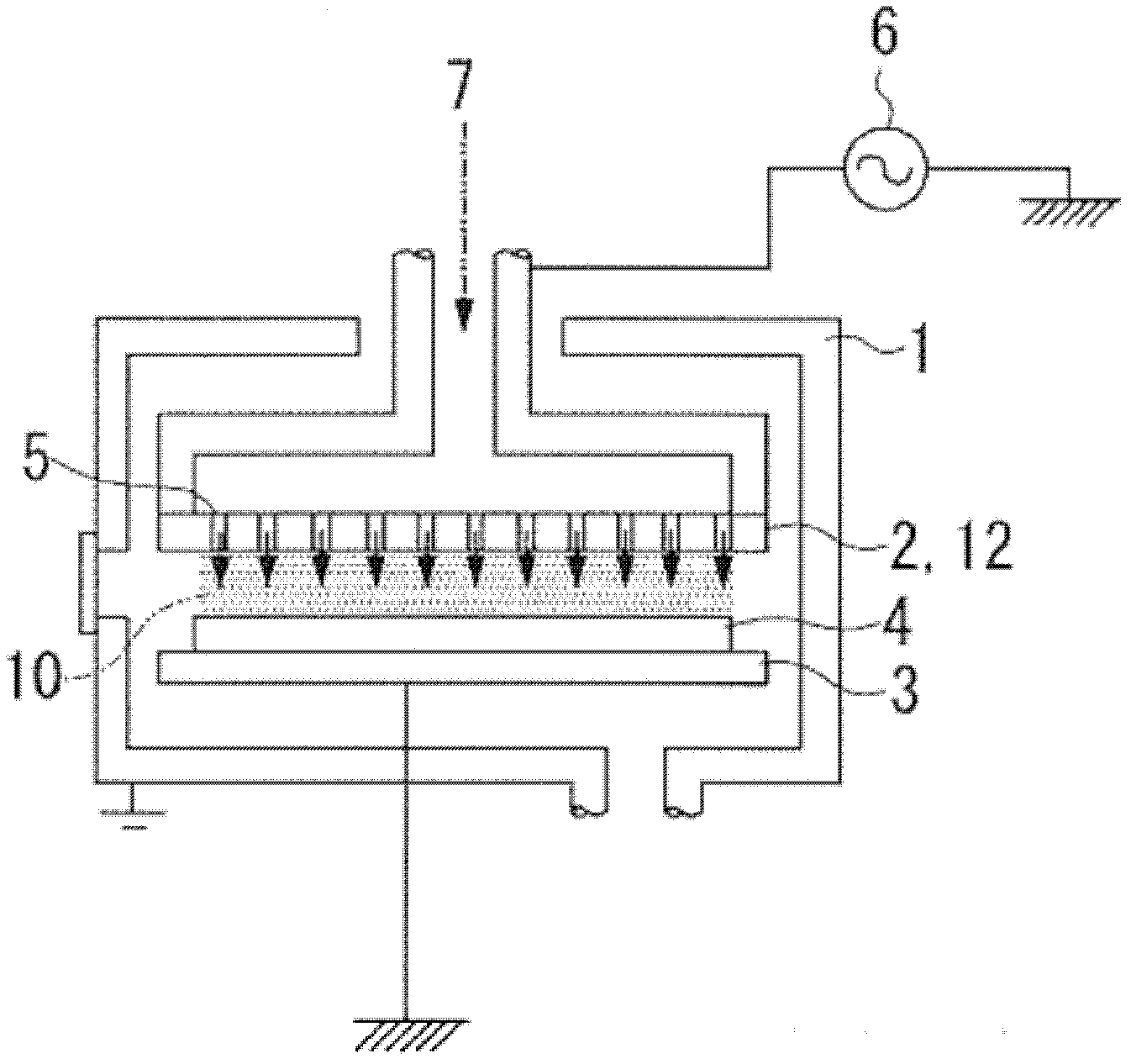
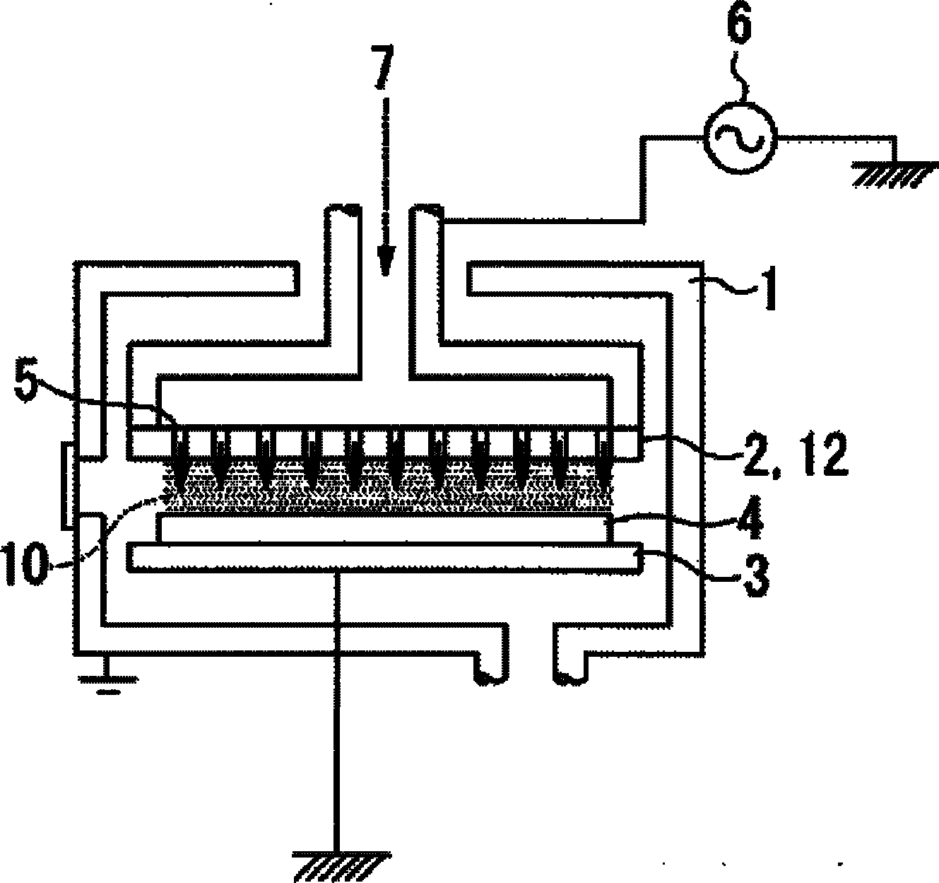
technical field [0001] The present invention relates to a silicon electrode plate for plasma etching that improves the in-plane uniformity of plasma etching. Background technique [0002] Usually, such as figure 1 As shown, in a plasma etching apparatus for etching a silicon wafer used in the process of manufacturing a semiconductor integrated circuit, a silicon electrode plate 2 and a susceptor 3 are provided at intervals in a vacuum vessel 1 . In this plasma etching apparatus, a silicon wafer 4 is placed on a susceptor 3, and while an etching gas 7 flows toward the silicon wafer 4 through the through pores 5 provided on the silicon electrode plate 2, it is injected into the silicon electrode plate by a high-frequency power supply 6. 2 and the base 3 with a high-frequency voltage applied, the plasma 10 is generated in the space between the silicon electrode plate 2 and the base 3 by applying the high-frequency voltage, and the plasma 10 is based on the physical reaction of...

Claims


Application Information

Patent Timeline
Patent Type & Authority Applications(China)
IPC IPC(8): H01J37/04H01J37/32
CPCH01J37/3255H01L21/3065
Inventor 米久孝志高畠康太
Owner MITSUBISHI MATERIALS CORP
Learn More