
Trap lamp with combined light sources and preparation method thereof

A technology of combining light source and trapping lamp, applied in the direction of light source, light source combination, light source fixing, etc., can solve the problems of high energy consumption, short lifespan, trapping and so on of ultraviolet fluorescent lamps, and achieves reduction of light shielding effect, improvement of lifespan, and expansion of the spectral range. Effect

Inactive Publication Date: 2012-08-01
江苏勇仕照明股份有限公司
View PDF6 Cites 6 Cited by
  • Summary
  • Abstract
  • Description
  • Claims
  • Application Information

AI Technical Summary

Problems solved by technology

Existing insect trap lamps usually use ultraviolet fluorescent lamps with a single light source as the light source for attracting insects. Due to the different phototaxis of different types of insects, many insects cannot be trapped by ultraviolet fluorescent lamps of the same wavelength, and some insects are resistant to long-wave light. Light, and ultraviolet fluorescent lamps have high energy consumption and short life

Method used


Image

  • Trap lamp with combined light sources and preparation method thereof
  • Trap lamp with combined light sources and preparation method thereof

Examples


Embodiment 1

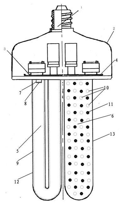
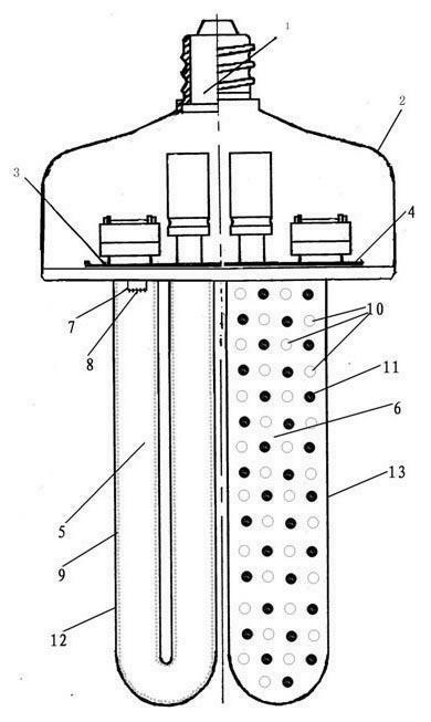
[0020] Such as figure 1 As shown, the present invention is made up of lamp cap 1, lamp holder 2, fluorescent lamp ballast 3, LED driving power supply 4, fluorescent lamp tube 5 and LED lamp tube 6; described fluorescent lamp tube 5 is made of glass tube 12 coated with fluorescent powder 9 1. A cathode filament 7 coated with an electron powder slurry 8 as an electron emission material;

[0021] The phosphor 9 is a mixture of phosphors with a peak wavelength of 330nm and 370nm, and its composition and the mass percentages of each component in the total phosphor are respectively 10-40% for 330nm phosphors and 60-90% for 370nm phosphors. %.

[0022] The shape of the fluorescent tube 5 is U-shaped, and the glass tube 12 is made of quartz.

[0023] The LED lamp tube 6 has a cylindrical appearance and is composed of green-emitting LED light sources 10 and blue-emitting LED light sources 11 that are evenly distributed in an interlaced manner. The peak wavelength of green light is 5...

Embodiment 2

[0032] A. Preparation of the phosphor layer: Weigh 20g of phosphor with a peak wavelength of 330nm, add 80g of phosphor with a peak wavelength of 370nm into a container with a mixer, add 55ml of deionized water, 75ml of binder, and 5g of reinforcing agent, turn on the mixer, Control the rotation speed at 160 rpm, stir for 6 hours, and control the density of the powder slurry to 1.45 g / cm3; apply the prepared phosphor to the inner wall of the glass tube 12, bake the coated glass tube 12, and bake the coated glass tube 12 at 500- Bake at 540°C for 10-30 minutes to prepare the glass tube 12 coated with the phosphor layer 6;

[0033] B. Preparation of the electronic powder slurry layer: Pour the electronic powder slurry into an automatic stirring container, put the cathode of the fluorescent lamp with the filament in the container containing the electronic powder slurry, and make the electron powder by electrophoresis or dip coating. The powder slurry is applied to the filament ...


PUM


Abstract

The invention discloses a trap lamp with combined light sources and a preparation method thereof. The trap lamp comprises a lamp holder, a lamp base, a fluorescent lamp ballast, an LED (light emitting diode) drive power source, a fluorescent tube and an LED tube, wherein the fluorescent tube comprises a glass tube and a cathode filament, wherein fluorescent powder is coated on the glass tube, and electronic powder paste as an electron emission material is coated on the cathode filament; and the LED tube comprises LED light sources for emitting green light, LED light sources for emitting blue light and a radiator. The trap lamp has the following beneficial effects: the trap lamp combines the ultraviolet fluorescent lamp light source and the LED light sources, solves the problems that the traditional trap lamps have narrow wavelength ranges, poor trapping effects and high energy consumption, has the characteristics of long life, many trapping varieties and wide spectral range, and achieves the aims of green lighting, resource conservation, energy conservation and environmental friendliness.

Description

technical field [0001] The invention relates to an illumination light source, in particular to an insect trap lamp with combined light source. Background technique [0002] With the continuous improvement of the requirements for the ecological environment, modern agriculture is gradually developing towards green agriculture, and the technical requirements for killing pests are also getting higher and higher. The traditional method of killing pests in agriculture is mainly to use chemical pesticides. Long-term repeated use of chemical pesticides makes pests resistant to pesticides, especially moths such as cotton bollworm, armyworm, corn scorpion, diamondback moth, noctuid moth, and bean hornworm. Pests are extremely resistant to pesticides. In order to eliminate pests, a large amount of pesticides have to be used, which has seriously damaged the ecological environment and caused harm to humans. In order to reduce the harm caused by spraying chemical pesticides and protect ...

Claims


Application Information

Patent Timeline
Patent Type & Authority Applications(China)
IPC IPC(8): A01M1/04H01J9/00H01J9/22F21V19/00F21Y113/00F21Y113/17F21Y113/20
Inventor 李永唐所明
Owner 江苏勇仕照明股份有限公司
Learn More