
Terminal plugging mechanism of automatic assembling machine of electric connector

An automatic assembly machine and electrical connector technology, which is applied to the assembly/disassembly of contacts, etc., can solve the problems of high labor intensity for operators, large consumption of human resources, and high defective rate of electrical connectors, so as to improve the competitiveness of enterprises , low probability of safety hazards, and the effect of reducing the consumption of human resources

Active Publication Date: 2012-07-25
BOLUO CHENGCHUANG PRECISION IND
View PDF6 Cites 13 Cited by
  • Summary
  • Abstract
  • Description
  • Claims
  • Application Information

AI Technical Summary

Problems solved by technology

[0005] In view of this, the present invention aims at the deficiencies in the prior art, and its main purpose is to provide a terminal insertion mechanism for an automatic electrical connector assembly machine, which can effectively solve the problem of manually inserting terminals when assembling the existing electrical connectors. The problems of low production efficiency, large consumption of human resources, high labor intensity of operators, high probability of relative safety hazards and high defect rate of electrical connectors

Method used


Image

  • Terminal plugging mechanism of automatic assembling machine of electric connector
  • Terminal plugging mechanism of automatic assembling machine of electric connector
  • Terminal plugging mechanism of automatic assembling machine of electric connector

Examples


Embodiment Construction

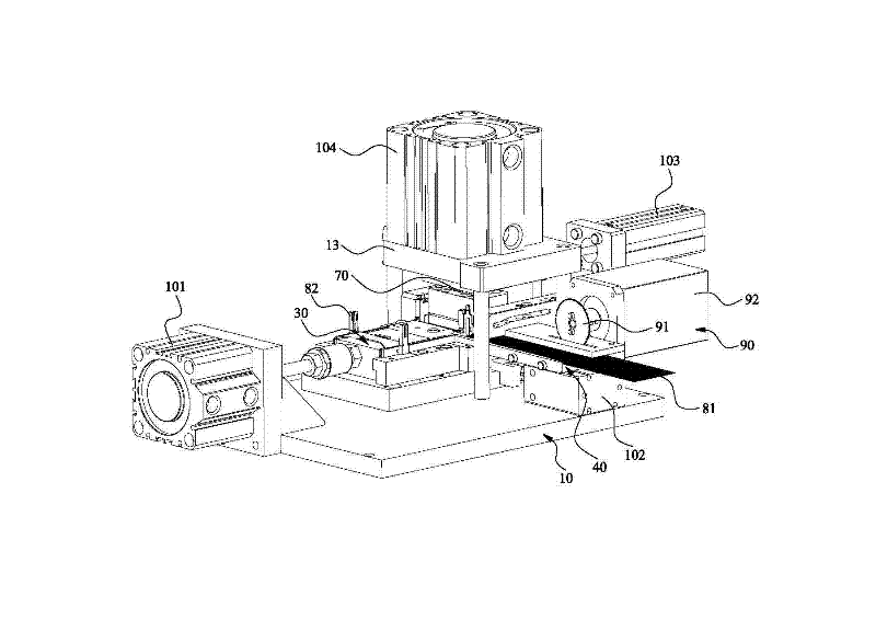
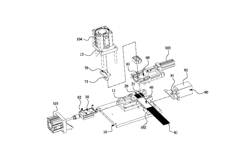
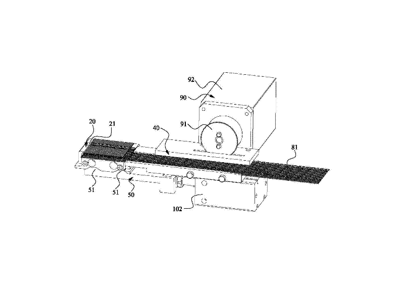
[0052] Please refer to Figure 1 to Figure 7 As shown, it shows the specific structure of the preferred embodiment of the present invention, including a base 10 and a terminal positioning seat 20 that can be floated up and down on the base 10, and a plastic plastic is provided around the terminal positioning seat 20 Component positioning seat 30, terminal feed rail 40, lifting block 50, crimping terminal sliding cover 60 and punch 70.

[0053] Wherein, the base 10 is provided with a sliding slot 11 and a hollow slot 12 , and the sliding slot 11 is located at the front side of the hollow slot 12 .

[0054] The terminal positioning seat 20 is located above the aforementioned hollow groove 12, and the terminal positioning seat 20 is provided with a blanking groove 21 and a terminal groove 22 for positioning the terminal 81. The blanking groove 21 communicates with the aforementioned hollow groove 12, and the terminal groove 22 Protrusions 201 of different lengths that conflict w...


PUM


Abstract

The invention discloses a terminal plugging mechanism of an automatic assembling machine of an electric connector, which comprises a base and a terminal locating base, wherein the terminal locating base is provided with a baiting groove and a terminal groove; the front end of the terminal groove is provided with bosses which abutted against a terminal sticking point and have difference lengths; a plastic cement piece locating base, a terminal feeding rail, a lifting block, a pressure terminal sliding cover and a plunger pin are arranged around the terminal locating base; drive devices are arranged directly at the plastic cement locating base, the lifting block, the pressure terminal sliding cover and the plunger pin; therefore, the lifting block, the pressure terminal sliding cover and the plunger pin are utilized so as to cut a terminal material belt; and sliding of the plastic cement piece locating base and the bosses which are arranged on the front end of the terminal groove and the have different lengths are utilized so as to plug the terminal according to a predetermined length. According to the invention, a traditional manually terminal plugging method is substituted, thus, product production efficiency is increased, human resource consumption is reduced, operation personnel workload is reduced; relative potential safety hazard probability is low; in addition, reject ratio of the electric connector can be also reduced; the terminal plugging mechanism disclosed by the invention is suitable for large-scale manufacture and production; and enterprise competitive power is enhanced.

Description

technical field [0001] The invention relates to the technical field of an automatic assembly machine for electrical connectors, in particular to a terminal insertion mechanism for an automatic assembly machine for electrical connectors. Background technique [0002] Electrical connectors are generally composed of three parts: plastic parts, terminals and metal housings, so the assembly of electrical connectors is to assemble the plastic parts, terminals and metal housings according to the determined relationship between the three. At present, the assembly of electrical connectors is generally carried out by manual or semi-automatic machines, and the process is relatively complicated. The main process steps include: [0003] First, the terminal is cut into a single PIN, and the terminal is pre-inserted into the plastic part manually, and then put into a manual punching fixture or a semi-automatic machine for riveting and fixing; then, the terminal strip is broken by hand; fin...

Claims


Application Information

Patent Timeline
IPC IPC(8): H01R43/20
Inventor 林宪登陈建华
Owner BOLUO CHENGCHUANG PRECISION IND
Learn More