
Antenna housing substrate and preparation method thereof

A cover substrate and radome technology, applied in the field of radome, can solve the problems of substrate dielectric constant, large dielectric loss, glass fiber dielectric constant and large dielectric loss, unsuitable for radome, etc., to achieve dielectric loss Small, low dielectric constant, promoting the effect of development

Inactive Publication Date: 2012-07-25
KUANG CHI INNOVATIVE TECH
View PDF3 Cites 21 Cited by
  • Summary
  • Abstract
  • Description
  • Claims
  • Application Information

AI Technical Summary

Problems solved by technology

At present, due to the limitation of the processing technology of the radome substrate, only the FR-4 board and the F4B board commonly used in the PCB industry can be used, but the support layer of the FR-4 board and the F4B board is generally made of glass fiber cloth, and the dielectric constant of the glass fiber Both the dielectric loss and the dielectric loss are large, resulting in a large dielectric constant and dielectric loss of the substrate, which is not suitable for use in radome

Method used


Image

  • Antenna housing substrate and preparation method thereof
  • Antenna housing substrate and preparation method thereof
  • Antenna housing substrate and preparation method thereof

Examples


Embodiment 1

[0019] Mix high-density polyethylene with a mass ratio of 85% and silica hollow microspheres with a mass ratio of 15%, use injection molding technology to process the radome substrate, perform surface treatment on the radome, and vacuum sputter a layer on its surface metal copper, such as figure 1 Embodiment 1 The radome substrate preparation method flow chart is shown.

[0020] It should be understood that in this embodiment, adding hollow silica beads to the formulation can reduce the density of the radome substrate, reduce the dielectric loss of the plate, and lower its dielectric constant.

[0021] It should be understood that in this embodiment, parameters such as the thickness of the radome substrate and the density of the radome substrate during the injection molding process may be controlled as required.

[0022] It should be understood that in this embodiment, a layer of metal copper is vacuum sputtered on the surface of the radome substrate in order to continue etch...

Embodiment 2

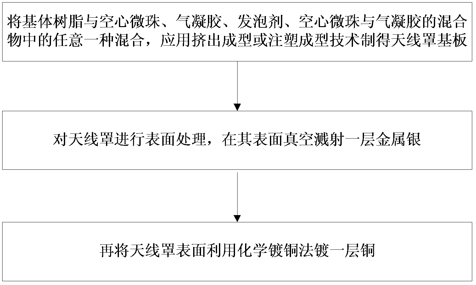
[0025] Mix polypropylene with a mass ratio of 75% and silica airgel with a mass ratio of 25%, process it into a radome substrate by extrusion molding process, carry out surface treatment on the radome substrate, and vacuum sputter on its surface A layer of metallic silver, and then a layer of copper film is plated on the silver-plated radome substrate by electroless copper plating.

[0026] It should be understood that copper-plating the radome substrate after vacuum sputtering metallic silver is to increase the thickness of the radome substrate to meet specific requirements.

[0027] It should be understood that electroless copper plating is an inherently catalytic redox reaction. First, treat the insulating substrate with an activator, so that a layer of active particles is adsorbed on the surface of the insulating substrate. Usually, metal palladium particles are used. Copper ions are reduced on these active metal palladium particles, and these reduced metal copper crystal ...


PUM


Abstract

The invention provides an antenna housing substrate and a preparation method thereof. The antenna housing substrate is prepared by mixing substrate resin with any one of hollow microspheres, aerogel, a foaming agent and mixture of the hollow microspheres and the aerogel and applying an extrusion forming or injection molding technology. The antenna housing substrate prepared by the method is provided with no glass fiber reinforcing layer, so that the dielectric loss is low, the dielectric constant is low; meanwhile, substrates of different performances can be prepared through design of the formula; the industrial production requirements are met; and the antenna housing substrate has good development and application prospect.

Description

【Technical field】 [0001] The invention relates to the field of radome, in particular to a radome substrate and a preparation method thereof. 【Background technique】 [0002] Antennas are usually placed in an open-air environment and are subject to storms, ice, snow, dust, and solar radiation in nature at any time, resulting in greatly reduced antenna accuracy, shortened service life, and poor reliability during operation. The radome is a structure that protects the antenna system from the harsh external environment. It absorbs and reflects the electromagnetic waves radiated by the antenna, changes the energy distribution of the antenna in free space, and affects the electrical performance of the antenna to a certain extent. Therefore, the antenna Electrically, the cover should have a good electromagnetic wave radiation transmission function to reduce the loss of electromagnetic waves. At present, due to the limitation of the processing technology of the radome substrate, onl...

Claims


Application Information

Patent Timeline
Patent Type & Authority Applications(China)
IPC IPC(8): C08L23/06C08L23/12C08L55/02C08L27/06C08L69/00C08L25/06C08K13/04C08K7/26C08K7/24C08K13/06C08K9/00C08K3/36C08J9/06C08J9/12H01Q1/42
Inventor 刘若鹏赵治亚方小伟金晶
Owner KUANG CHI INNOVATIVE TECH
Learn More