


Quick Research
Generate reliable direction feasibility study reports for your R&D in just a few steps.

Technical Q&A
Discover and master advanced knowledge NOW. Basics, ideas, possibilities, all at once.

Find Solutions
As an expert in R&D theories, this can generate solutions to your technical problems instantly.

Evaluate Feasibility
Analyze your overall solution with one click, know your potential R&D risks in advance.

Monitor Landscape
Get weekly tech updates, stay abreast of the latest tech innovations and key insights.
Hydrophobization fuel cell expanded graphite flow field and manufacturing method thereof
A technology of expanded graphite and fuel cells, which is applied in the field of electrochemical cells, can solve problems such as uneven gas distribution in the battery pack, water accumulation, and MEA flooding, so as to reduce MEA flooding, reduce water management pressure, and improve The effect of utilization
- Summary
- Abstract
- Description
- Claims
- Application Information
AI Technical Summary
Problems solved by technology
Method used
Image

Examples
Embodiment 1
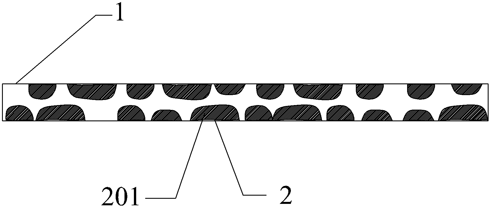
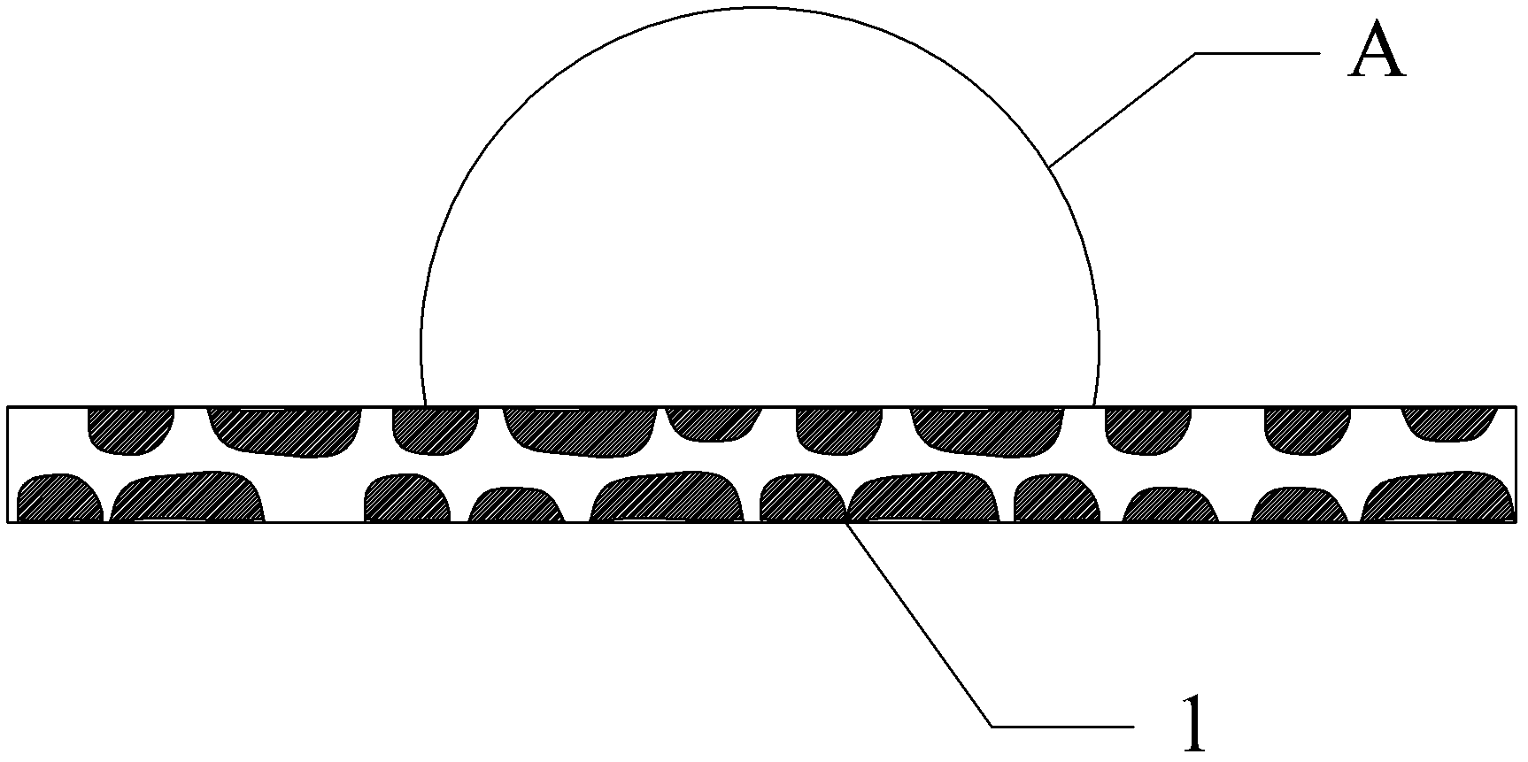
[0033] Put 20 sheets of porous expanded graphite material 1 with a thickness of 3 mm into the sealed tank for vacuuming, when the vacuum degree in the sealed tank reaches 10 -2 Stop vacuuming during pa, suck the polytetrafluoroethylene suspension (solvent is water) that concentration is 1% in the sealed box that expanded graphite material 1 is housed, make expanded graphite material 1 soak wherein 10min; The graphite material 1 is taken out, and the resin on the surface of the expanded graphite material 1 is absorbed by absorbent paper, and cured at 340°C to 360°C for 3 hours. Form a layer of filling layer I201 (such as figure 1 shown), forming a layer of hydrophobic network. Show by test, the massfraction of the polytetrafluoroethylene resin that contains in the expanded graphite material 1 after processing is 2.6%; In hydrophobic test, the contact angle of expanded graphite material 1 surface after filling is 99.6 (as image 3 shown, where A is a water droplet). 20 sheets...
Embodiment 2
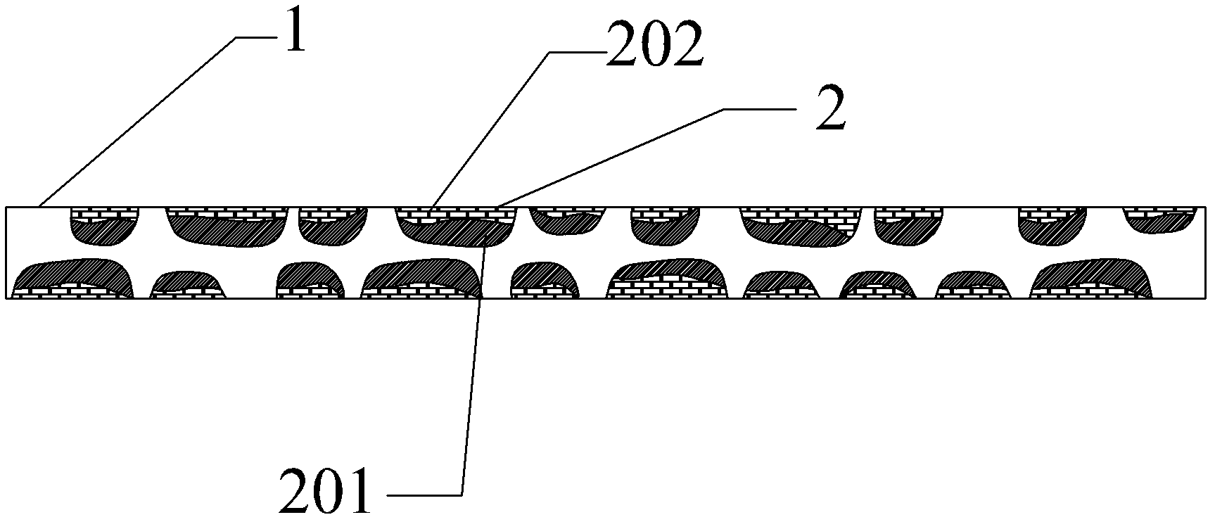
[0035] Put 20 sheets of porous expanded graphite material 1 with a thickness of 3 mm into the sealed tank for vacuuming, when the vacuum degree in the sealed tank reaches 10 -2 Stop vacuuming during pa, suck the polytetrafluoroethylene suspension (solvent is water) that concentration is 1% in the sealed box that expanded graphite material 1 is housed, make expanded graphite material 1 soak wherein 10min; The graphite material 1 is taken out, and the liquid on the surface of the expanded graphite material 1 is sucked away by absorbent paper, and cured at 340°C to 360°C for 3 hours. After curing, the immersed polytetrafluoroethylene is fixed with the expanded graphite material 1, thereby Form a layer of filling layer I201 (such as figure 1 As shown), that is, a hydrophobic network is formed; then the expanded graphite material 1 after the above treatment is put back into the sealed tank for vacuum treatment, and when the vacuum degree in the sealed tank reaches 10 -2 Stop vacuu...
PUM
| Property | Measurement | Unit |
|---|---|---|
| quality score | aaaaa | aaaaa |
Abstract
Description
Claims
Application Information
 - R&D Engineer
- R&D Manager
- IP Professional
- Industry Leading Data Capabilities
- Powerful AI technology
- Patent DNA Extraction
Browse by: Latest US Patents, China's latest patents, Technical Efficacy Thesaurus, Application Domain, Technology Topic, Popular Technical Reports.
© 2024 PatSnap. All rights reserved.Legal|Privacy policy|Modern Slavery Act Transparency Statement|Sitemap|About US| Contact US: help@patsnap.com