
Temperature measuring device of machine tool

A temperature measurement and machine tool technology, applied in the direction of measuring device, thermometer, measuring heat, etc., can solve the problems of the influence of machine tool movement, the failure of temperature monitoring, the disconnection of the connecting line, etc., to achieve a convenient and fast fixing method, improve temperature measurement accuracy, and The effect of temperature monitoring

Inactive Publication Date: 2012-07-04
ZHEJIANG UNIV
View PDF5 Cites 20 Cited by
  • Summary
  • Abstract
  • Description
  • Claims
  • Application Information

AI Technical Summary

Problems solved by technology

The wired connection method is easy to affect the movement of the machine tool. When the machine tool is moving, it is easy to break the connecting line or cause internal breakage of the connecting line, which directly leads to the failure of temperature monitoring.
However, the existing temperature sensors using wireless communication are large in size and cannot be stably fixed to the moving parts of the machine tool. Especially when the moving parts are fed at high speed, they are not suitable for monitoring the thermal characteristics of the machine tool.
[0007] In the existing machine tool temperature detection, the contact force between the temperature sensor and the point to be measured cannot be guaranteed. Due to the contact thermal resistance between different contact surfaces, if a certain pressure cannot be guaranteed between the temperature sensor and the point to be measured, it will make If the thermal resistance between the two contact surfaces is too large, there will be a temperature gradient between the temperature sensor and the point to be measured, resulting in poor accuracy of the measured temperature

Method used


Image

  • Temperature measuring device of machine tool
  • Temperature measuring device of machine tool
  • Temperature measuring device of machine tool

Examples


Embodiment 1

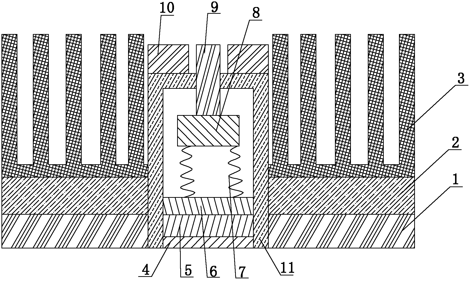
[0037] Such as figure 1 Shown, a kind of machine tool temperature measuring device comprises:

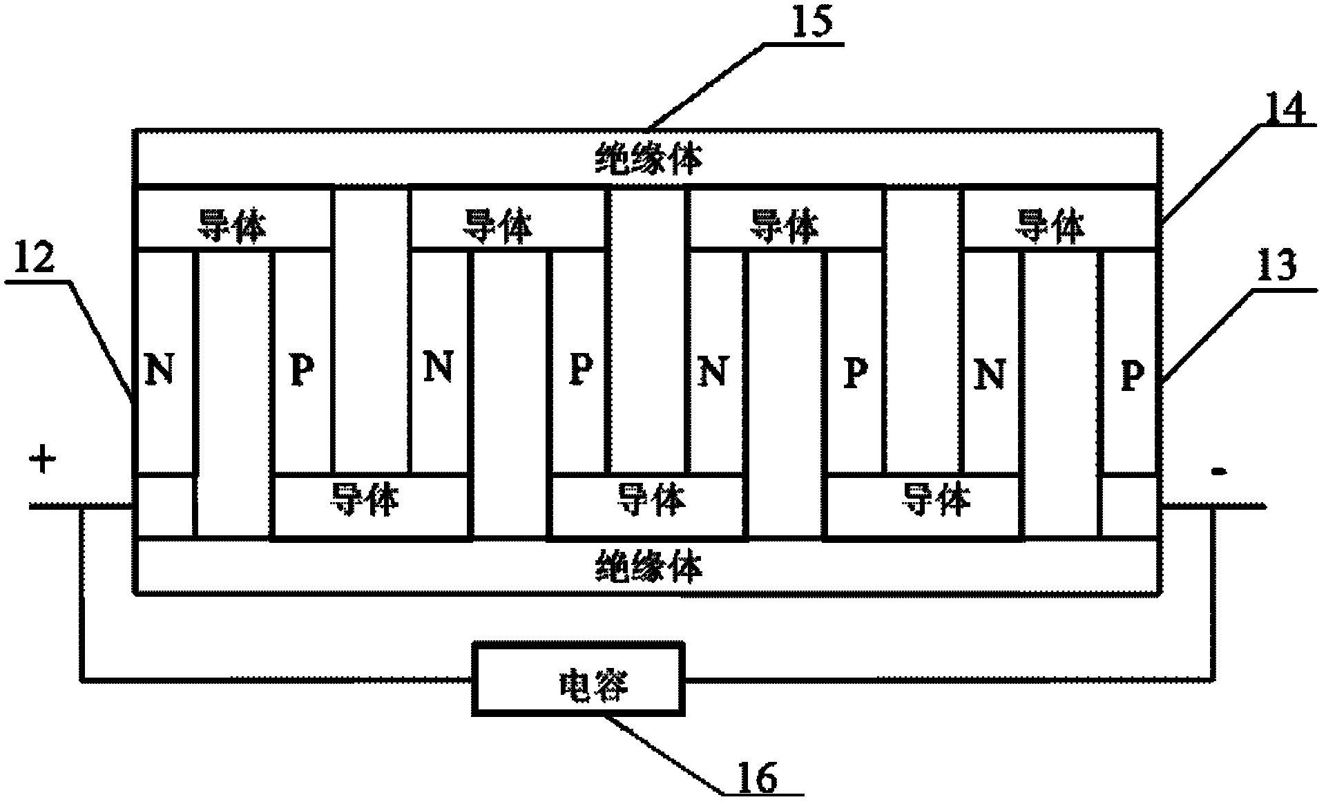
[0038] The magnetic connector 1, the magnetic connector 1 is specifically selected from the magnetic steel mainly composed of NdFeB metal alloy, one side of the magnetic connector 1 is used for fixed connection with the surface of the machine tool to be tested, and the other side of the magnetic connector 1 is fixed with The thermoelectric power generation module 2, the side of the thermoelectric power generation module 2 connected to the magnetic connector 1 is used as the high temperature end of the thermoelectric power generation module 2, and the side of the thermoelectric power generation module 2 away from the magnetic connector 1 is fixed with a heat sink 3, which is used for the heat sink 3 Dissipate heat at the low temperature end of the thermoelectric power generation module 2 . The magnetic connector 1, the thermoelectric power generation module 2 and the heat sink 3 are...


PUM


Abstract

The invention discloses a temperature measuring device of a machine tool. The temperature measuring device comprises a temperature sensor, a conditioning circuit and a power supply, wherein the temperature sensor is used for collecting the temperature of the machine tool; the conditioning circuit is used for processing the output signals of the temperature sensor; the temperature measuring deviceis provided with a vacuum heat insulation sleeve which is used for packaging the temperature sensor; and the vacuum heat insulation sleeve is fixed on the machine tool through a magnetic connection piece. According to the invention, the influences to the temperature sensor by the neighboring environment temperature variation are prevented through the vacuum heat insulation sleeve, thus the accurate measurement of the temperature of the surface to be tested is realized; electricity is supplied for a radio transmission module and a conditioning circuit board through a thermoelectricity power generation module, the use of a battery is prevented, the compact volume of the whole temperature measuring device of the machine tool is ensured, and the using of the self-power-supply mode is more environmentally friendly; and the technical problems that the connection wire is easy to snap or the inner part of the connection wire is cracked in the existing connection mode are solved through the radio transmission module.

Description

technical field [0001] The invention relates to the field of temperature measurement of machine tools, in particular to a self-powered machine tool temperature measurement device for machine tools. Background technique [0002] The machining accuracy of CNC machine tools is an important indicator to measure the performance of CNC machine tools. A large number of studies have shown that thermal errors are the largest error source of precision machining machinery such as CNC machine tools, accounting for about 70% of the total error. For ultra-precision CNC machine tools , even reaching nearly 90%. Due to the inevitable existence of internal and external heat sources in the machining process of CNC machine tools, especially internal heat sources, it will inevitably lead to thermal deformation errors. Therefore, it is very important to monitor the thermal characteristics of CNC machine tools, perform corresponding deformation compensation according to its temperature change, a...

Claims


Application Information

Patent Timeline
IPC IPC(8): G01K7/00G05B19/404
Inventor 贺永傅建中姚鑫骅沈洪垚赵朋陈子辰
Owner ZHEJIANG UNIV
Learn More