
Displaying method for austenite grain boundary of intermediate-carbon alloy rare earth steel

An austenite grain boundary and carbon alloy technology, applied in the field of physical inspection, can solve the problems of long erosion time, unknown display effect of medium carbon alloy steel, low efficiency, etc., to avoid environmental pollution, ensure product performance, and be reasonable The effect of controlling process parameters

Inactive Publication Date: 2012-06-20
INNER MONGOLIA BAOTOU STEEL UNION
View PDF4 Cites 10 Cited by
  • Summary
  • Abstract
  • Description
  • Claims
  • Application Information

AI Technical Summary

Problems solved by technology

[0003] Chinese patent CN86105938 discloses "a new method for displaying grain boundaries of copper-rare earth alloys". The main commonly used etchant preferentially etches the rare earth elements in copper, which brings insurmountable difficulties to the research and observation of the solid solution and distribution of rare earth elements in copper.
The disadvantage is that it only shows good effect on the austenite grain boundary of copper-rare earth alloy, but it is not known about medium carbon alloy steel.
The disadvantage is that the sample erosion time is as long as 40-60 minutes, and the efficiency is low; the display effect of medium carbon alloy steel is unknown
The disadvantage is that it is suitable for medium and high carbon steel, and it is not mentioned whether it is suitable for medium carbon alloy steel and rare earth steel

Method used


Image

  • Displaying method for austenite grain boundary of intermediate-carbon alloy rare earth steel
  • Displaying method for austenite grain boundary of intermediate-carbon alloy rare earth steel
  • Displaying method for austenite grain boundary of intermediate-carbon alloy rare earth steel

Examples


Embodiment 1

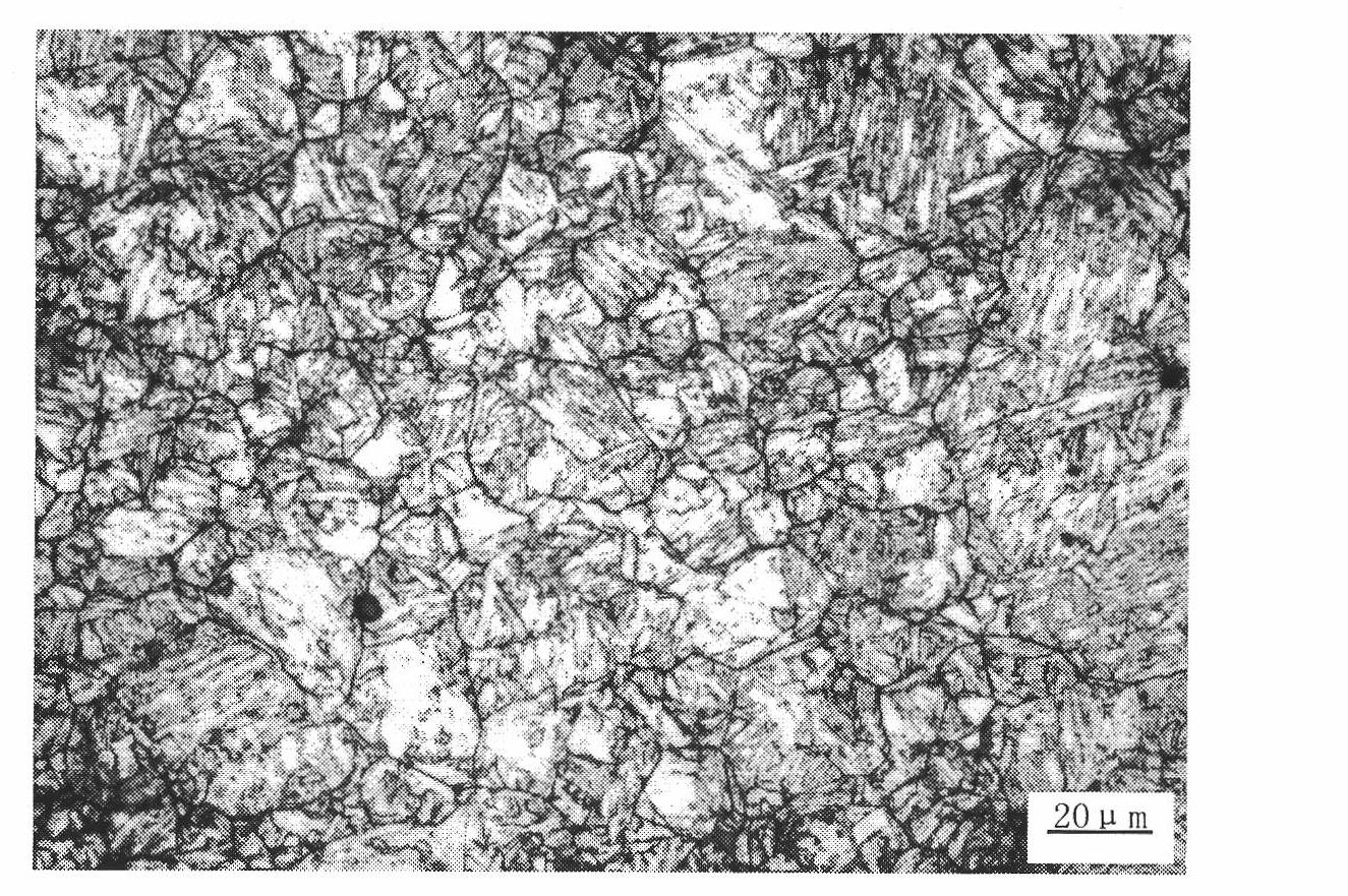
[0019] The chemical composition of the sample is by weight percentage: C: 0.27%, Si: 0.190%, Mn: 0.565%, P: 0.0098%, S: 0.010%, Cr: 1.13%, Mo: 0.228%, V: 0.056%, B: 0.0027, Re: 0.002% belong to medium carbon alloy steel;

[0020] The specific erosion method is:

[0021] (1), sample preparation: after quenching, the iron oxide scale on the surface of the sample with a size of 20 mm × 15 mm × 15 mm was ground off, and then finely ground on metallographic sandpaper with a grain size of 240, 400, 600, 800, and 1000, Grinding and polishing on a polishing machine should ensure that the polished surface of the sample is free from any scratches, pits, pits, stains and other defects.

[0022] (2) Proportion of corrosive reagents and erosion method: Put 2 g of picric acid and 20 ml of detergent into a φ60 mm×70 mm petri dish containing 20 ml of distilled water, stir with a glass rod to allow the reagents to fully react; after stirring, put the absorbent cotton Put it into the bottom o...

Embodiment 2

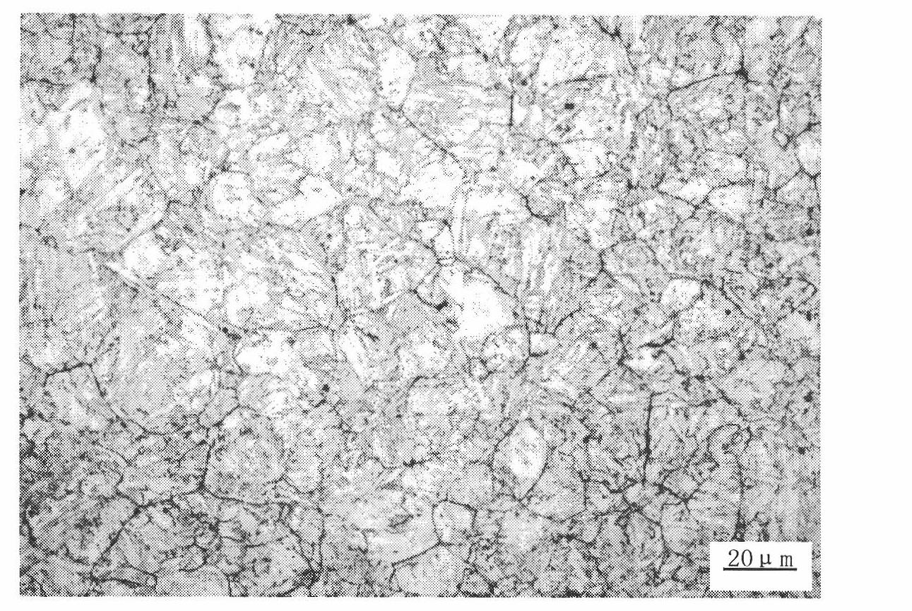
[0024] The chemical composition of the sample is by weight percentage: C: 0.274%, Si: 0.201%, Mn: 0.561%, P: 0.0084%, S: 0.009%, Cr: 1.14%, Mo: 0.230%, V: 0.058%, B: 0.0026, Re: 0.004% belong to medium carbon alloy steel;

[0025] The specific erosion method is:

[0026] (1), sample preparation: prepare sample according to the method for preparing sample in embodiment 1,

[0027] (2) Proportion of corrosive reagents and erosion method: Put 2 g of picric acid and 20 ml of detergent into a φ60 mm×70 mm petri dish containing 20 ml of distilled water, stir with a glass rod to allow the reagents to fully react; after stirring, put the absorbent cotton Put it into the bottom of the petri dish; at this time, put the polished sample into the petri dish with the polished side down, take out the sample after eroding for 5 minutes, put it in a large amount of alcohol to wash the sample, and immediately wipe the surface mucous membrane with absorbent cotton , and finally washed and drie...

Embodiment 3

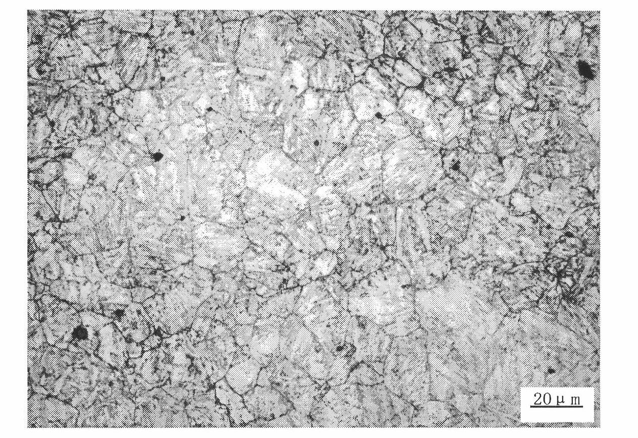
[0029] The chemical composition of the sample is by weight percentage: C: 0.273%, Si: 0196%, Mn: 0.559%, P: 0.0086%, S: 0.009%, Cr: 1.18%, Mo: 0.229%, V: 0.057%, B: 0.0025, Re: 0.006% belong to medium carbon alloy steel;

[0030] The method for preparing the sample The preparation of the sample and the erosion method are the same as in Example 1. Put 2 g of picric acid and 20 ml of detergent into a φ60 mm×70 mm petri dish filled with 20 ml of distilled water, and stir with a glass rod to allow the reagents to fully react; After stirring, put the absorbent cotton into the bottom of the petri dish; at this time, put the polished sample into the petri dish with the polished side facing down, take out the sample after eroding for 5 minutes, put it in a large amount of alcohol to wash the sample, and wash the sample with absorbent cotton Immediately wipe its surface mucous membrane, rinse and dry with alcohol at last, and observe under a metallographic microscope at 200 times magni...


PUM


Abstract

The invention provide a displaying method for austenite grain boundary of intermediate-carbon alloy rare earth steel, belongs to the technical field of physical detection and is used for solving the problem that intermediate-carbon alloy rare earth steel can not clearly display austenite grains. The displaying method is characterized by comprising the steps of: preparing a corrosive according to the following reagent ratio: 20 mL of distilled water, 1-2 g of picric acid and 10-20 mL of Xigujing; preparing a sample, wherein the ground and polished surface of the sample is guaranteed to have no scratch, pock, pit, stain and other defects; adding the corrosive to a culture dish according to the reagent ratio, stirring with a glass rod so that the reagents are sufficiently reacted, and after stirring, placing absorbent cotton at the bottom of the culture dish; and placing the ground and polished sample in the culture dish with the ground surface downward, taking out the sample after the sample is eroded for 5 min, rinsing the sample in a great deal alcohol, immediately wiping the surface mucous membrane of the sample with the absorbent cotton, washing with alcohol, blow-drying and observing under a metallurgical microscope. According to the invention, a specific corrosive and an appropriate corroding method are adopted, so that the austenite grain boundary can be clearly displayed.

Description

technical field [0001] The invention belongs to the technical field of physical detection, in particular to a method for displaying austenite grain boundaries in medium-carbon alloy steel Background technique [0002] The austenite grain size of steel has a great influence on the strength, toughness and fatigue performance of steel. It plays an important role in studying the evolution law of material structure in the process of steel production, reasonably controlling process parameters and ensuring product performance. Therefore, the detection of austenite grain size is of great significance, and its display method has been continuously explored, innovated and improved by the majority of industry insiders. Whether the austenite grains can be clearly displayed depends on many factors such as the chemical composition of the sample, the state of heat treatment, the etching time, the etching method, and the etching reagent. Commonly used display methods mainly include thermal ...

Claims


Application Information

Patent Timeline
Patent Type & Authority Applications(China)
IPC IPC(8): G01N1/32
Inventor 姜海龙杨雄马爱清董珍石晓霞宋江波张行刚
Owner INNER MONGOLIA BAOTOU STEEL UNION
Learn More