
Pneumatic tire for vehicle

A technology for pneumatic tires and vehicles, applied to vehicle parts, tire parts, tire treads/tread patterns, etc., can solve problems such as detrimental handling characteristics, detrimental dry braking characteristics, and reduced circumferential rigidity to achieve good performance Wetting and slippery properties, good dry handling properties, frizz-free effect

Active Publication Date: 2015-01-21
CONTINENTAL REIFEN DEUTSCHLAND GMBH
View PDF4 Cites 0 Cited by
  • Summary
  • Abstract
  • Description
  • Claims
  • Application Information

AI Technical Summary

Problems solved by technology

Here too, there is a greater crimpability of the profiled block elements about radial and axial axes as well as about a circumferential axis parallel to the circumferential direction, which may undesirably impair both Dry braking characteristics also impair handling characteristics
In addition, with this configuration, the circumferential rigidity is additionally reduced due to the alternate positioning.

Method used


Image

  • Pneumatic tire for vehicle
  • Pneumatic tire for vehicle
  • Pneumatic tire for vehicle

Examples


Embodiment Construction

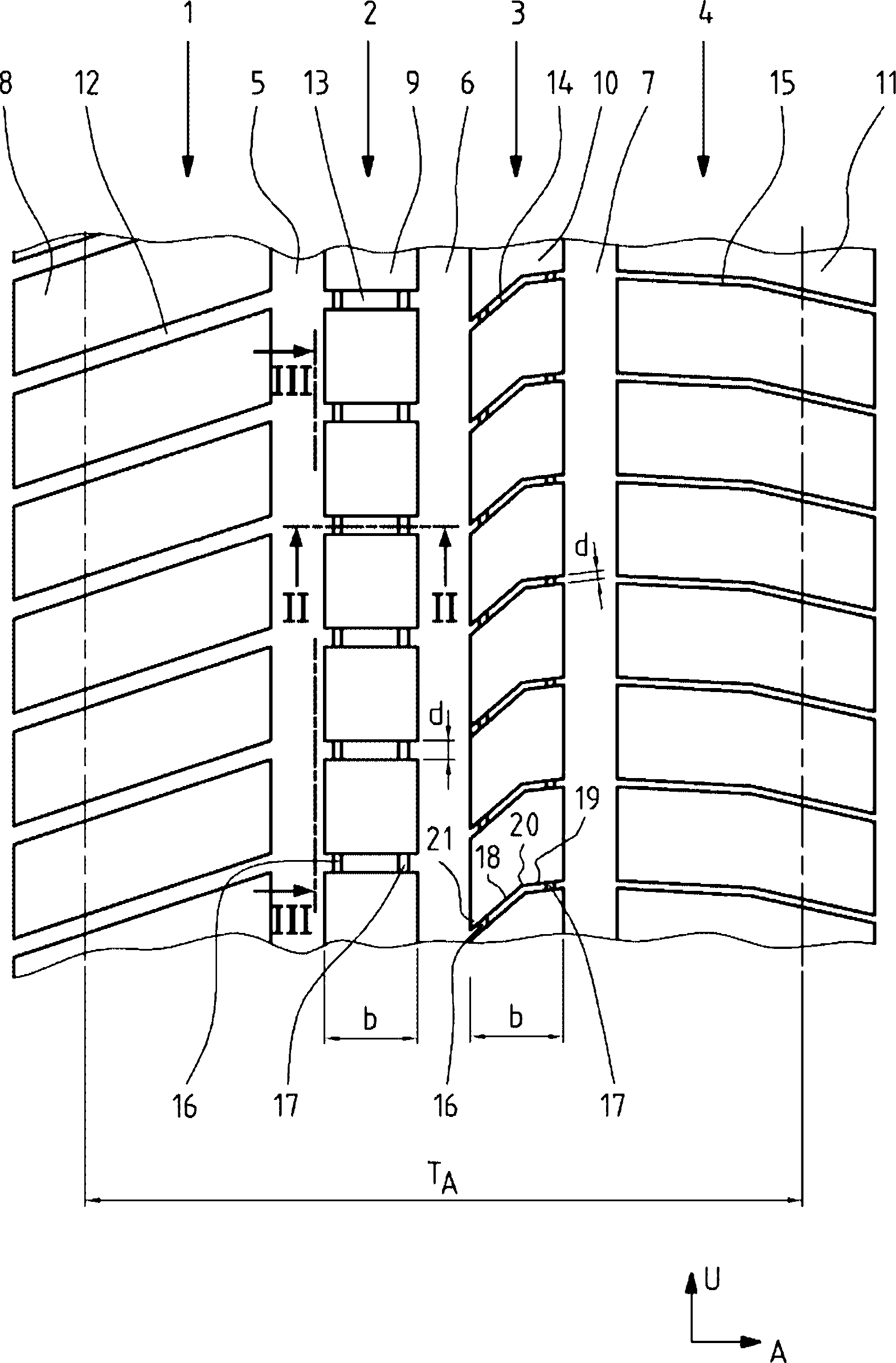
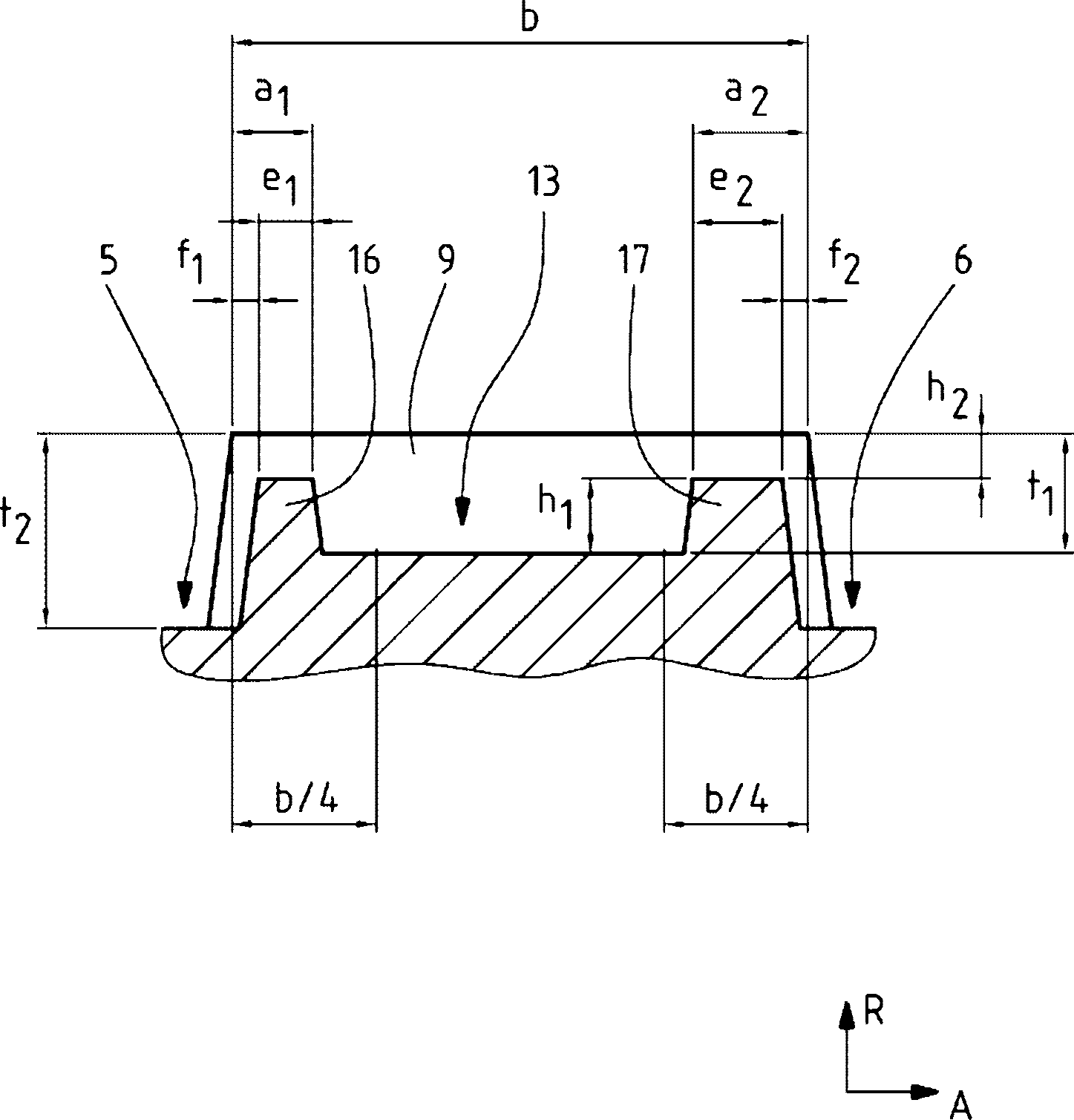
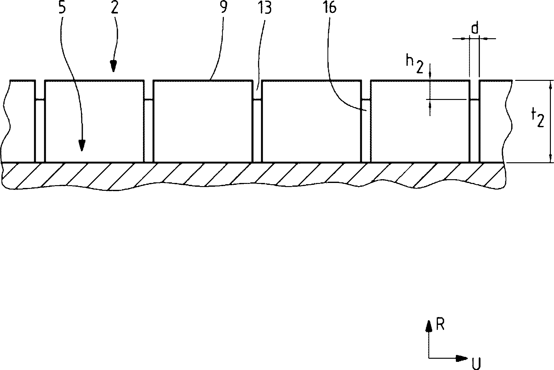
[0043] Figure 1 to Figure 3 The tread stripes of a vehicle pneumatic tire for a passenger car in radial configuration are shown. The tread stripes are summer treads.

[0044] exist figure 1 Shown from left to right in , the tread stripes are composed of shaped block rows 1, 2, 3 and 4 arranged successively in the axial direction A. Forming block rows 1 and 4 are shoulder forming block rows. The shaped block rows 1 to 4 respectively extend along the circumferential direction U of the vehicle pneumatic tire over the entire circumference of the vehicle pneumatic tire. The profiled block rows 1 and 2 are formed such that they are spaced apart from each other in the axial direction A by a prior art circumferential groove 5 , which is oriented in the circumferential direction U and extends over the entire circumference. The profiled block row 2 and the profiled block row 3 are formed such that they are spaced from each other in the axial direction A by a prior art circumferenti...


PUM


Abstract

The invention relates to a pneumatic tire for an automobile having tread lug rows, each being interspaced in an axial direction by a peripheral groove, and wherein at least one tread lug row (2, 3) is configured to include a transverse groove (13, 14) of interspaced tread lug elements (9, 10). In each transverse groove (13, 14) of the tread lug row (2, 3), in the respective two axial outer border areas of the transverse groove (13, 14) within the footprint width TA, a connecting piece (16, 17) elevated from the groove bottom of the transverse groove (13, 14) is formed extending in a peripheral direction U, and interconnecting the two tread lug elements (9, 10) interspaced by the transverse groove.

Description

technical field [0001] The invention relates to a vehicle pneumatic tire, in particular for passenger cars, having a tread pattern with radially raised tread bands extending over the circumference of said vehicle pneumatic tire (e.g. rows of shaped blocks or circumferential ribs), the tread bands are respectively separated from each other in the axial direction by a circumferential groove extending on the circumference of the vehicle pneumatic tire, where in the axial direction A At least one column of shaped blocks having a width b measured inside the ground-bearing width is composed of a plurality of shaped blocks arranged successively in the circumferential direction U of the vehicle pneumatic tire and correspondingly separated from each other by a transverse groove Composition of block elements. Background technique [0002] Such pneumatic tires for vehicles are well known. Here, the transverse grooves make it possible to receive and discharge water when the tire impre...

Claims


Application Information

Patent Timeline
Patent Type & Authority Patents(China)
IPC IPC(8): B60C11/13B60C11/04
CPCB60C11/13B60C11/1263B60C11/1369B60C11/0306
Inventor 乌尔里希·贝尔马库斯·菲舍尔
Owner CONTINENTAL REIFEN DEUTSCHLAND GMBH
Learn More