Waste treatment equipment

A technology for processing equipment and waste, applied in special forms of dry distillation, coke ovens, petroleum industry, etc., can solve the problems of low temperature, complicated systems, adverse effects on the properties of cement clinker, etc., to ensure stability and restrain temperature fluctuations. Effect

Active Publication Date: 2012-05-16
KAWASAKI HEAVY IND LTD +4
View PDF2 Cites 4 Cited by
  • Summary
  • Abstract
  • Description
  • Claims
  • Application Information

AI Technical Summary

Problems solved by technology

[0004] That is to say, in the above prior art example, the pyrolysis gas generated by the gasifier can be used as part of the fuel gas, and carbon and ash can be used as cement raw materials at the same time, but the two must be separated, and another The system is provided to cement manufacturing equipment, so there are difficulties in complicated systems
[0005] In addition, the calorific value of waste is usually about 1000-3000 kcal / kg, which is lower than that of the fuel usually used in cement kilns (in the case of using medium, the calorific value of low-grade medium is 5000-7000 kcal / kg). , so when the pyrolysis gas from garbage is used together, the temperature in the kiln is low, and the fuel consumption may be unsatisfactory.
[0006] Moreover, the water vapor contained in the pyrolysis gas from garbage may have adverse effects on the properties of cement clinker, and when the pyrolysis gas is burned in a cement kiln, hot spots may occur to form deposits

Method used


Image

  • Waste treatment equipment
  • Waste treatment equipment
  • Waste treatment equipment

Examples


Embodiment Construction

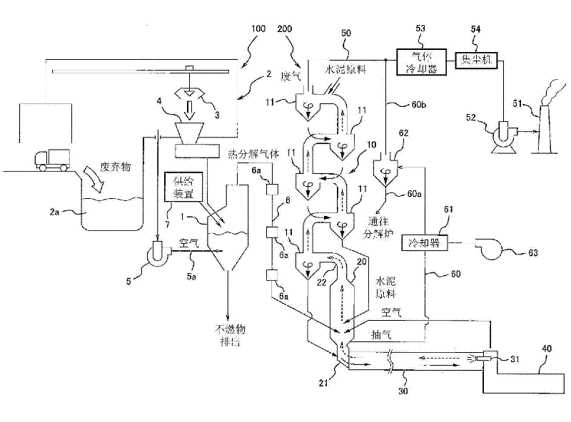
[0054] Preferred embodiments of the present invention will be described below with reference to the drawings. figure 1 It is an overall system diagram of the waste disposal facility 100 of the first embodiment and the cement manufacturing facility 200 installed adjacent thereto. The waste treatment facility 100 shown on the left side of the figure thermally decomposes waste in the gasification furnace 1, and the generated gas (pyrolysis gas) is mixed and burned in the cement firing process. The amount of the pyrolysis gas is, for example, 20,000 to 30,000 Nm 3 / h, compared with the exhaust gas volume of the cement manufacturing equipment 200 shown in the figure (for example, 300,000 Nm 3 / h) is much less, so that the waste treatment plant 100 can be installed in the vicinity of an existing cement plant with little modification.

[0055] ―Waste disposal facilities―

[0056] In the waste processing facility 100 , for example, general waste from households, industrial waste in...


PUM


Abstract

The present invention relates to waste treatment equipment. The purpose of the present invention is to solve the following technical problem that: under the following conditions, the operating safety of cement manufacturing equipment (200) is ensured, wherein the conditions comprise: thermal decomposition gas generated by a gasifier (1) is conveyed to a decomposition furnace (20) of the cement manufacturing equipment (200) under the condition of maintenance of the constant carbon content and the constant ash content in the thermal decomposition gas, and the like. The technical scheme of the present invention is that: waste treatment equipment (100) is arranged close to the cement manufacturing equipment (200). The waste treatment equipment comprises: the gasifier (1) and a gas conveying pipeline (6), wherein the gasifier is provided for carrying out the gasification reaction for the waste to generate the thermal decomposition gas, and the gas conveying pipeline is provided for conveying the generated thermal decomposition gas to the decomposition furnace (20) under the condition of the constant carbon content and the constant ash content in the thermal decomposition gas. According to the present invention, a flow ratio of the thermal decomposition gas from the gasifier (1) to the discharged waste gas from the decomposition furnace (20) is limited below the specified flow ratio, such that the temperature change of the decomposition furnace (20) can be inhibited so as to ensure the stability of the cement manufacturing equipment during the operating process.

Description

technical field [0001] The present invention relates to a waste treatment facility for sanitation treatment of waste by using a cement decomposition furnace installed adjacent to a cement manufacturing facility. Background technique [0002] In recent years, even in developing countries, for example, with the improvement of living standards, there is an increasing need for sanitary treatment of garbage, and the increase in the amount of incineration treatment is also expected, but there are also general construction garbage The incinerator requires a large cost and requires a long construction period. In addition, it is necessary to evaluate the impact of the incinerator on the surrounding environment and disclose information to nearby residents, so it takes a long time to prepare before the start of construction. Furthermore, in Japan there is still a shortage of landfill sites for burying the ashes generated by incinerators. In the case of establishing a new waste disposa...

Claims


Application Information

Patent Timeline
IPC IPC(8): C04B7/43C10B53/00
Inventor 郭文叁李顺安张长乐李群峰肖杰玉林敏和井上英二片畑正加藤定史市谷升
Owner KAWASAKI HEAVY IND LTD
Why Eureka
Try Eureka