Method for treating circulating water
A treatment method and technology for circulating water, applied in the fields of water/sewage multi-stage treatment, water/sludge/sewage treatment, chemical instruments and methods, etc. To achieve the effect of reducing corrosion, saving cost and good treatment effect
- Summary
- Abstract
- Description
- Claims
- Application Information
AI Technical Summary
Problems solved by technology
Method used
Image
Examples
Embodiment 1
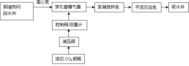
[0033] Such as figure 1 As shown, the Jiujiang steel slag hot stuffy circulating water treatment process, the specific steps are as follows:
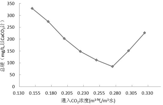
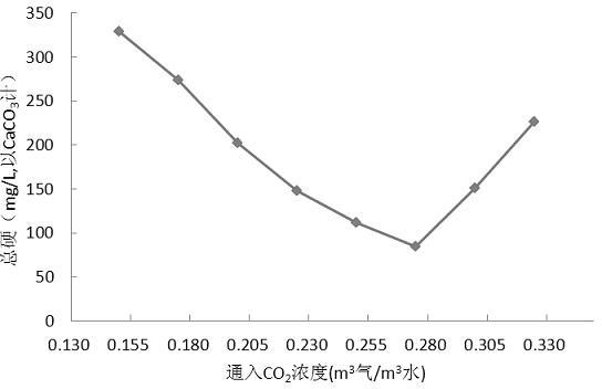
[0034] Step 1: The backwater in the steel slag hot and stuffy backwater well enters the perforated tube aerator through the centrifugal pump; at the same time, the CO 2 Enter the perforated tube through the pressure reducing valve, control valve and flow meter; the CO 2 For industrial liquid CO 2 , the amount of feed is determined by the amount of return water, water quality and the PH value of the outlet water of the advection sedimentation tank; in this test, CO 2 Concentrations up to 0.25 m 3 Gas / m 3 water;
[0035] Step 2: Mix in CO 2 The backwater enters the flocculation stirring tank for flocculation and sedimentation; the Ca(OH) in the backwater 2 In the flocculation stirred tank, with CO 2 The reaction takes place to generate CaCO 3 Precipitation; CO 3 2- with CO 2 Reacts with water to form HCO 3 - ;
[0036] Step...
Embodiment 2
[0042] Before treatment, the pH index of the backwater from the hot stuffy backwater well was 11.89, the water temperature was 63°C, and the total hardness was 760.32 mg / L, OH - Alkalinity is 584.45 mg / L, CO 3 2- Alkalinity 115.62 mg / L, total dissolved solids 1740 mg / L, electrical conductivity 3400 μs / cm, suspended solids concentration 150 mg / L;
[0043] The method for processing backwater is the same as in Example 1, and CO 2 The concentration is 0.20 m 3 Gas / m 3 Water, settling time 1 h, effluent pH value 10.91, total hardness 144.94 mg / L, OH - Alkalinity is 41.04 mg / L, CO 3 2- The alkalinity was 112.33 mg / L, the total dissolved solids was 365 mg / L, and the conductivity was 749 μs / cm.
Embodiment 3
[0045] Before treatment, the pH value of hot stuffy return water of steel slag was 11.98, the water temperature was 67°C, and the total hardness was 837.64 mg / L, OH - Alkalinity is 675.05 mg / L, CO 3 2- The alkalinity is 183.61 mg / L, the total dissolved solids is 1853 mg / L, the conductivity is 3590 μs / cm, and the concentration of suspended solids is 254 mg / L.
[0046] The method for processing backwater is the same as that in Example 1, the CO 2 The concentration is 0.28 m 3 Gas / m 3 water, settling time 1 h, effluent pH value 10.04, total hardness 84.08 mg / L, CO 3 2- Alkalinity is 21.60 mg / L, HCO 3 - The alkalinity was 32.40 mg / L, the total dissolved solids was 220 mg / L, and the conductivity was 455 μs / cm.
PUM
| Property | Measurement | Unit |
|---|---|---|
| hardness | aaaaa | aaaaa |
| hardness | aaaaa | aaaaa |
| thickness | aaaaa | aaaaa |
Abstract
Description
Claims
Application Information
 - R&D
- Intellectual Property
- Life Sciences
- Materials
- Tech Scout
- Unparalleled Data Quality
- Higher Quality Content
- 60% Fewer Hallucinations
Browse by: Latest US Patents, China's latest patents, Technical Efficacy Thesaurus, Application Domain, Technology Topic, Popular Technical Reports.
© 2025 PatSnap. All rights reserved.Legal|Privacy policy|Modern Slavery Act Transparency Statement|Sitemap|About US| Contact US: help@patsnap.com


