
Optical fiber wireless RoF passive optical network realizing method based on optical code division multiplexing

A passive optical network, division multiplexing technology, applied in the field of optical communication

Inactive Publication Date: 2012-04-11
UNIV OF ELECTRONICS SCI & TECH OF CHINA
View PDF5 Cites 23 Cited by
  • Summary
  • Abstract
  • Description
  • Claims
  • Application Information

AI Technical Summary

Problems solved by technology

[0006] In order to overcome the deficiencies of the prior art, the present invention provides a method for implementing an optical fiber wireless RoF passive optical network with high confidentiality based on OCDM to solve the seamless integration of wired and wireless services in the access network field and wired and wireless user terminals High security and confidentiality requirements for required information, so as to meet people's requirements for business service diversification and communication quality, security and confidentiality in the real society

Method used


Image

  • Optical fiber wireless RoF passive optical network realizing method based on optical code division multiplexing
  • Optical fiber wireless RoF passive optical network realizing method based on optical code division multiplexing
  • Optical fiber wireless RoF passive optical network realizing method based on optical code division multiplexing

Examples


Embodiment 1

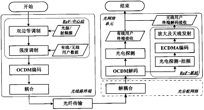
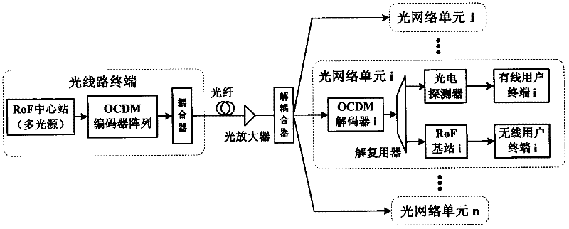
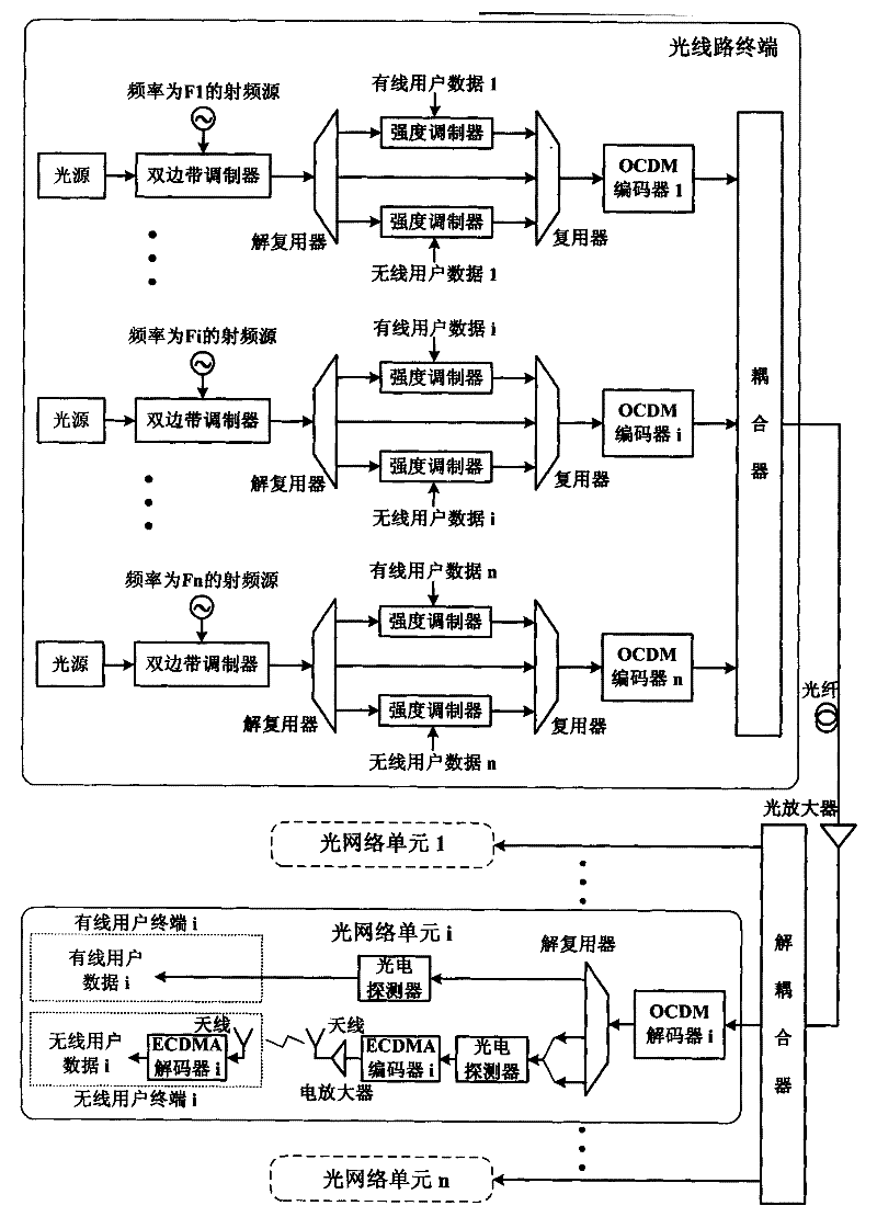
[0040] The principle block diagram and the detailed structural block diagram of the embodiment of the present invention 1 are respectively as figure 2 and image 3 As shown, the first feature of this implementation example is that the OLT is used to generate an optical carrier, modulate a wired / wireless user signal, perform OCDM encoding processing, and couple the encoded n-channel optical signals together to transmit them to an optical fiber link. The optical fiber link is used to transmit the optical signal emitted by the OLT. Optical amplifiers are used to amplify optical signals transmitted in fiber optic links. The decoupler is used to divide the received optical signal into n paths and send them to each ONU. Multiple ONUs are used to receive optical signals transmitted by optical fiber links, OCDM decoding processing, photoelectric detection, ECDMA encoding processing, and respectively transmit wired / wireless signals to wired / wireless user terminals. The second featu...

Embodiment 2

[0048] The principle block diagram and the detailed structural block diagram of the embodiment of the present invention 2 are respectively as Figure 4 and Figure 5 As shown, the first feature of this implementation example is that: the OLT is used to generate optical carriers, modulate wired / wireless user signals, perform OCDM encoding processing, and couple the encoded n-channel optical signals together to transmit them to optical fiber links. The optical fiber link is used to transmit the optical signal emitted by the OLT. Optical amplifiers are used to amplify optical signals transmitted in fiber optic links. The ODN is used to divide the received optical signal into several branches and decode the optical signal of each branch. Multiple ONUs are used to receive optical signals transmitted by optical fiber links, photoelectric detection, ECDMA encoding, and transmit wired / wireless signals to wired / wireless user terminals respectively. The second feature is that the sin...


PUM


Abstract

The invention discloses an optical fiber wireless RoF passive optical network realizing method based on an optical code division multiplexing (OCDM). In an optical line terminal (OLT) RoF center station, a signal realizes double-sideband modulation, three paths of generated carrier components are respectively modulated with wired and wireless user data and are not subjected to modulation. The signal is coupled to an optical fiber channel after coded by the OCDM, transmitted to an optical distribution network (ODN) and allocated to each optical network unit (ONU). The ONU carries out OCDM decoding on the received signal, then three paths of components are separated, one path of components is directly sent to a wired user terminal after subjected to photoelectric detection, the other two paths of components enter an RoF base station for carrying out beat frequency to obtain a radio frequency signal, the radio frequency signal is subjected to ECDMA (Electric Code Division Multiple Access) coding and transmitted through an antenna after subjected to electric amplification, and a wireless user terminal obtains a required signal through ECDMA decoding. The invention provides an effective path for realizing wired / wireless secrecy access in a PON (Passive Optical Network) system.

Description

technical field [0001] The invention belongs to the technical field of optical communication, and more specifically relates to an optical code division multiplexing (OCDM)-based wireless communication over optical (RoF) passive optical network system. Background technique [0002] In recent years, with the rapid development of computer, communication and other technologies, the demand for various services such as video-on-demand, digital TV, and teleconferencing has been increasing, and the traditional copper access network obviously cannot meet this requirement. This has led to the rapid development of broadband optical fiber access network technology and has become a research hotspot in the field of communication technology. It has been more than 10 years since the concept of Passive Optical Network (PON) appeared in the mid-1990s. The PON system adopts a point-to-multipoint tree topology, that is, an Optical Line Terminal (OLT) passes through an Optical Distribution Netw...

Claims


Application Information

Patent Timeline
IPC IPC(8): H04Q11/00H04J14/00
Inventor 张崇富陈晨
Owner UNIV OF ELECTRONICS SCI & TECH OF CHINA
Learn More