
Thermoelectric conversion element and thermoelectric conversion module

A technology of thermoelectric conversion and components, which is applied in the direction of electrical components, thermoelectric device parts, and thermoelectric device manufacturing/processing, etc., which can solve the problems of low durability, trouble, and inclination of thermoelectric conversion element electrodes, etc., to achieve guaranteed temperature difference, Effect of improving durability, big temperature difference

Inactive Publication Date: 2012-02-01
TOKYO UNIVERSITY OF SCIENCE +1
View PDF4 Cites 6 Cited by
  • Summary
  • Abstract
  • Description
  • Claims
  • Application Information

AI Technical Summary

Problems solved by technology

[0006] In addition, since the thermoelectric conversion elements are joined to the electrodes one by one by brazing such as soldering (handatsu) or brazing (ろう付), each thermoelectric conversion element tends to incline with respect to the electrodes.
Once the thermoelectric conversion element is tilted, the thermal expansion of the element itself may cause the thermoelectric conversion element to peel off from the electrode or cause cracks on the thermoelectric conversion element
Therefore, conventional thermoelectric conversion elements have problems of poor yield and low durability.
[0007] In addition, since the thermoelectric conversion elements are connected to the electrodes one by one, it takes a lot of time to manufacture the thermoelectric conversion module and the mass productivity is low.

Method used


Image

  • Thermoelectric conversion element and thermoelectric conversion module
  • Thermoelectric conversion element and thermoelectric conversion module
  • Thermoelectric conversion element and thermoelectric conversion module

Examples


Embodiment Construction

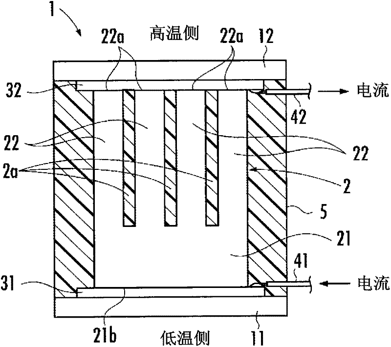
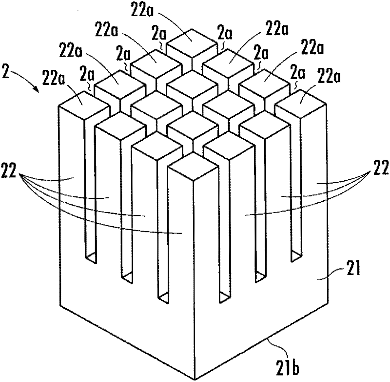
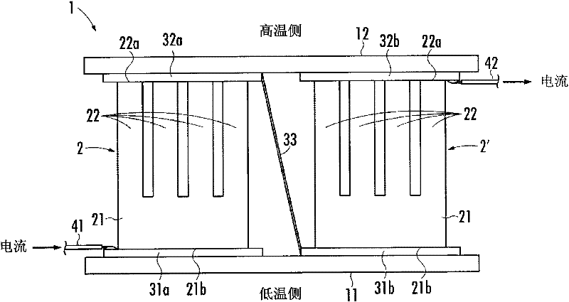
[0035] Reference figure 1 with figure 2 The thermoelectric conversion module using the thermoelectric conversion element according to the first embodiment of the present invention will be described, and the thermoelectric conversion module is used for power generation. The thermoelectric conversion module of the first embodiment includes a pair of substrates 11, 12 molded of alumina and having insulating properties, and first and second electrodes 31 made of copper plates and provided on the surfaces of the substrates 11, 12 opposite to each other. 32, and the magnesium silicide (Mg silicide) arranged between the two electrodes 31 and 32 2 Si) n-type thermoelectric conversion element 2.

[0036] In the prior art, materials BiTe, PbTe, and CoSb are used as materials for thermoelectric conversion elements. However, all these materials are harmful to the human body (including possibly harmful) and are expensive. Magnesium silicide (Mg 2 Si) is harmless to the human body, has littl...


PUM


Abstract

Disclosed is a thermoelectric conversion element which has improved yield and improved durability, can ensure a satisfactory level of difference in temperature between both end parts readily, can be connected to an electrode easily without inclining, and has improved mass productivity. Also disclosed is a thermoelectric conversion module comprising the thermoelectric conversion element. Specifically disclosed is a thermoelectric conversion element (2) comprising: multiple pillar-like sections (22) in each of which one end is electrically connected to a first electrode plate (32) and which are arranged at a given spacing from each other; and a joining section (21) which connects the other ends of the pillar-like sections (22) to each other and is electrically connected to a second electrode plate (31). A connection surface (21b) of the joining section (21) which is connected to the second electrode plate (31) has a larger surface area than the total surface area of end parts (22a) of the pillar-like sections (22).

Description

Technical field [0001] The present invention relates to a thermoelectric conversion module that uses the Seebeck effect to generate electricity or uses the Peltier effect to cool or heat, and a thermoelectric conversion element used in the thermoelectric conversion module. Background technique [0002] In the prior art, the following n-type thermoelectric conversion element is known (for example, refer to Japanese Patent Laid-Open No. 11-274578). A plurality of the n-type thermoelectric conversion elements are arranged between two electrodes of a thermoelectric conversion module having a pair of substrates and a pair of electrodes, one end of the n-type thermoelectric conversion element is electrically connected to one of the electrodes, and the other end is connected to the other The electrodes are electrically connected. Wherein, the pair of electrodes are respectively provided on opposite surfaces of each substrate. [0003] According to the thermoelectric conversion element d...

Claims


Application Information

Patent Timeline
Patent Type & Authority Applications(China)
IPC IPC(8): H01L35/32H01L35/08H01L35/14H01L35/34H02N11/00
CPCH01L35/08H01L35/32H10N10/817H10N10/17
Inventor 饭田努小国阳平根本崇佐藤纯一
Owner TOKYO UNIVERSITY OF SCIENCE
Learn More