A concrete delivery pipe and its manufacturing method

A technology for concrete conveying pipes and elbows, used in siphons, pipe elements, flange connections, etc.

Inactive Publication Date: 2011-12-28
李宗仙
View PDF5 Cites 21 Cited by
  • Summary
  • Abstract
  • Description
  • Claims
  • Application Information

AI Technical Summary

Problems solved by technology

Wear-resistant cast steel elbows are commonly used now, and the outer bending part is thickened to ensure the overall wear cycle, so as to reduce material waste and improve wear resistance, but in fact, the increase in weight does not increase its overall wear resistance
[0004]Curved and straight pipes commonly used today are generally formed by integral casting, and the wear resistance and high toughness cannot be optimally matched, and it is easy to wear out or burst the pipe
[0005]The outer tubes of the commonly used composite elbows are mostly cast, and the production cost is high due to the thin wall and difficult to form, so it is not easy to produce in batches
At the same time, the wear-resistant pipe is integrally cast and formed. When the concrete of one elbow moves to the other, it will cause the impact and wear failure of the elbow port.
[0006] Now the commonly used conical pipe is pressed into two semicircles by steel plate, then surfacing welding, welding flange forming, the process is complicated, because the surfacing layer is prone to cracks, resulting in surfacing wear-through failure
[0007]The commonly used straight pipes are formed by welding flanges of MnB and MnCr seamless steel pipes, and then the inner wall is hardened by induction quenching. Tube burst, or wear-through failure due to uneven quenching
Generally, the inner sleeve of the straight pipe is designed to have a length of about 30mm. When the concrete in the bent pipe is transported to the straight pipe, the surface to be tested will be impacted. Because the inner sleeve is too short, the straight pipe cannot be protected.

Method used


Image

  • A concrete delivery pipe and its manufacturing method
  • A concrete delivery pipe and its manufacturing method
  • A concrete delivery pipe and its manufacturing method

Examples


Embodiment Construction

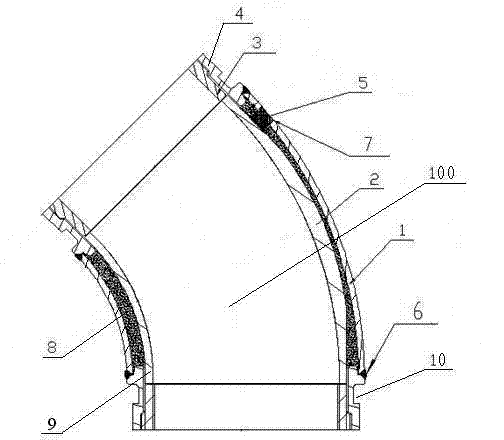
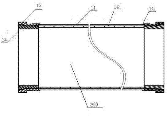
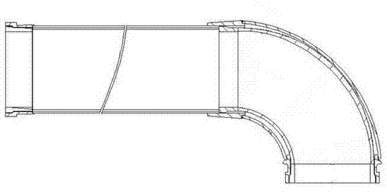
[0034] Such as Figure 1-Figure 13 As shown, the concrete delivery pipe includes an elbow 100 and a straight pipe 200, and the straight pipe 200 is connected to the elbow 100; Set in the curved outer pipe 1, there is a filling layer 8 between the curved wear-resistant pipe 2 and the curved outer pipe 1, the curved pipe flange 4 is connected to the curved outer pipe 1, and the curved pipe flange 4 has a curved pipe inner sleeve 3, Bonding between the elbow inner sleeve 3 and the elbow flange 4 . The straight pipe 200 includes a straight wear-resistant pipe 12, a straight outer pipe 11 and a straight pipe flange 13, the straight wear-resistant pipe 12 is placed in the straight outer pipe 11, and the straight wear-resistant pipe 12 is bonded to the straight outer pipe 11; The pipe flange 13 is connected with the straight outer pipe 11, and the straight pipe flange 13 has a straight pipe inner sleeve 14, and the straight pipe inner sleeve 14 is bonded to the straight pipe flange ...


PUM


Abstract

A concrete conveying pipe, including a bend pipe and a straight pipe, the bend pipe includes a bend wear-resistant pipe, a bend outer pipe and a bend pipe flange, the bend wear-resistant pipe is set in the bend outer pipe, and the bend wear-resistant pipe and the bend outer pipe With a filling layer, the elbow flange is connected to the outer elbow pipe, and the inner elbow flange has an inner elbow sleeve; the straight pipe includes a straight wear-resistant pipe, a straight outer pipe and a straight pipe flange, and the straight wear-resistant pipe is placed on the straight outer In the pipe; the straight pipe flange is connected with the straight outer pipe, and the straight pipe flange has a straight pipe inner sleeve. Bend wear-resistant pipes, straight wear-resistant pipes and inner sleeves of bent pipes and inner sleeves of straight pipes are made of new hypereutectic high-chromium white cast iron materials, which are formed by investment mold, sand mold or centrifugal casting to meet the requirements of high wear resistance; The pipe and straight outer pipe are formed by hot push or cold drawing of low-carbon high-strength steel pipe, which has the characteristics of low cost and easy forming. The contradiction between high toughness and high wear resistance.

Description

technical field [0001] The invention relates to engineering machinery, in particular, it provides a concrete delivery pipe used in a concrete delivery pump and a manufacturing method thereof. Background technique [0002] Concrete conveying pipe (including bent pipe, straight pipe, bent straight pipe and tapered pipe, the same below) is a conveying pipe applied to the arm frame and chassis of the mixed soil pump truck, and can also be applied to the concrete drag pump. The medium is concrete (a slurry composed of cement, gravel, and fine sand), which is a wearing part. Once worn out, it needs to be replaced, which often causes interruption of continuous work and frequent replacement of worn parts, resulting in a decrease in work efficiency. affect the construction period of the project. [0003] Since the amount of wear is proportional to the load, according to the analysis of the wear parts and the principle of hydrodynamics, the impact on the outer bend is the largest, a...

Claims


Application Information

Patent Timeline
Patent Type & Authority Applications(China)
IPC IPC(8): F16L43/00F16L23/00F16L25/14F16L57/06
Inventor 李宗仙
Owner 李宗仙
Why Eureka
Try Eureka