
Servo-controlled hydraulic vibration excitation system for high-speed rail track subgrade testing

A servo control and track technology, applied in the direction of fluid pressure actuation system components, fluid pressure actuation devices, mechanical equipment, etc., can solve the problem that the excitation system is difficult to meet the requirements of high-speed rail track roadbed testing, and it is difficult to meet the high vibration frequency at the same time. and high excitation force, large hydraulic system flow, etc., to achieve the effect of good system dynamic response, small dynamic load, and small hydraulic system flow

Inactive Publication Date: 2011-11-30
INST OF ROCK AND SOIL MECHANICS - CHINESE ACAD OF SCI +1
View PDF7 Cites 15 Cited by
  • Summary
  • Abstract
  • Description
  • Claims
  • Application Information

AI Technical Summary

Problems solved by technology

The pump-controlled motor vibration system is driven by the variable hydraulic pump to rotate the hydraulic motor, and the hydraulic motor drives the eccentric block to rotate, which is fundamentally inertial vibration; the valve-controlled cylinder vibration system is to control the cylinder through the reversing valve to achieve vibration. It can start vibration under heavy load and can output a variety of waveforms, but the dynamic response is poor and the flow rate of the hydraulic system is large, so it is difficult to meet the requirements of high vibration frequency and high excitation force at the same time
[0005] It can be seen that the current excitation system is difficult to meet the requirements of high-speed rail track subgrade testing

Method used


Image

  • Servo-controlled hydraulic vibration excitation system for high-speed rail track subgrade testing
  • Servo-controlled hydraulic vibration excitation system for high-speed rail track subgrade testing
  • Servo-controlled hydraulic vibration excitation system for high-speed rail track subgrade testing

Examples


Embodiment Construction

[0029] The present invention will be further described below in conjunction with the accompanying drawings and specific embodiments, which are not intended to limit the protection scope thereof.

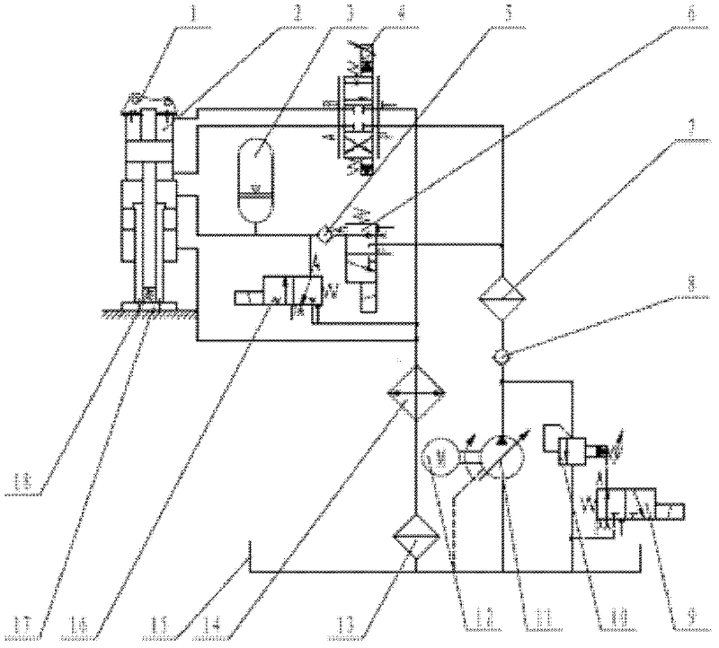
[0030] A servo-controlled hydraulic vibration excitation system for high-speed rail track subgrade testing. The system as figure 1 As shown: the oil pump 11 is coaxially connected with the motor 12, the oil suction port of the oil pump 11 communicates with the oil tank 15 through the oil pipe, and the oil pressure port of the oil pump 11 is connected to the oil inlet of the relief valve 10 and the inlet of the first check valve 8 through the oil pipe. The oil ports communicate with each other, the oil outlet of the overflow valve 10 communicates with the oil tank 15 through the oil pipe, the control port of the overflow valve 10 communicates with the A port of the second electromagnetic reversing valve 9, and the T port of the second electromagnetic reversing valve 9 It communicates...


PUM


Abstract

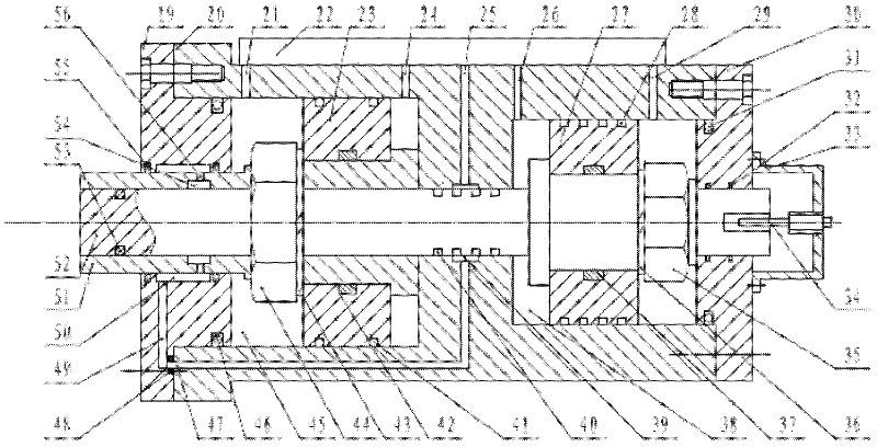
The invention relates to a servo-control hydraulic excitation system for a high-speed rail track roadbed test. The technical scheme of the invention is as follows: the oil press port of an oil pump (11) is respectively communicated with the P port of a servo valve (4) and the P port of a first magnetic exchange valve (6) through a first check valve (8) and a first filter (7); the A port and B port of the servo valve (4) are respectively correspondingly communicated with two working oil ports (26,29) of a dynamic pressure cavity (38) of a twin-stage servo hydraulic cylinder (2); the A port of the first magnetic exchange valve (6) is communicated with the oil inlet of a second check valve (5), the oil outlet of the second check valve (5) is respectively communicated with a second working oil port (24) of a static pressure cavity (45) of the twin-stage servo hydraulic cylinder (2), the A port of an electromagnetic ball valve (16) and an accumulator (3); and the working end of the twin-stage servo hydraulic cylinder (2) is connected with an excitation disc (17), and a right end cap (30) of the twin-stage servo hydraulic cylinder (2) is connected with a hydraulic excavator used for test. The servo-control hydraulic excitation system provided by the invention has the advantages of good dynamic response, small hydraulic system flow and good simulation effect, and meets the requirements of high excitation frequency and high exciting force simultaneously.

Description

technical field [0001] The invention belongs to a servo control hydraulic vibration excitation system. In particular, it relates to a servo-controlled hydraulic vibration excitation system for high-speed railway track subgrade testing. Background technique [0002] High-speed railway (hereinafter referred to as "high-speed railway") is the main development direction of railway construction in my country, but the lack of dynamic response test technology of track subgrade has seriously restricted the research and development of high-speed railway subgrade. At present, when studying the influence of the static load and the dynamic load of the train passing on the track subgrade at home and abroad, the mechanical inertial excitation system or the electro-hydraulic excitation system is mostly used. Due to the different materials of the subgrade, its natural frequency and other physical mechanics The characteristics are also different. It is required that the excitation frequency...

Claims


Application Information

Patent Timeline
IPC IPC(8): F15B21/12
Inventor 陈善雄曾良才陈新元姜领发湛从昌余飞傅连东秦尚林许锡昌陈昶龙万园郑飞龙雷斌
Owner INST OF ROCK AND SOIL MECHANICS - CHINESE ACAD OF SCI
Learn More