
Permanent magnet synchronous machine (PMSM) possessing assembled magnetic effect

A permanent magnet synchronous motor, the technology of action, applied in the synchronous motor with static armature and rotating magnet, magnetic circuit static parts, magnetic circuit rotating parts and other directions, can solve the requirements of distributed winding end length and rotating shaft material High, large magnetic flux leakage on the shaft side, etc., to achieve the effect of low probability of inter-turn short circuit fault, less copper consumption, and reduction of magnetic flux leakage at the end

Inactive Publication Date: 2011-11-23
SHANGHAI DIANJI UNIV
View PDF2 Cites 6 Cited by
  • Summary
  • Abstract
  • Description
  • Claims
  • Application Information

AI Technical Summary

Problems solved by technology

However, the use of distributed windings has the following disadvantages: (1) The ends of distributed windings are long and a lot of copper is wasted; (2) The leakage reactance is large; (3) It is difficult to get off the line and the structure is complicated
[0009] use image 3 and Figure 4 Although the permanent magnet synchronous motors with the rotor structure shown have a certain magnetic concentration effect, the magnetic flux leakage on the shaft side is large, and the non-magnetic bushing is required to isolate the magnetic field on the shaft side, and the material of the shaft is non-magnetic material. It has the following disadvantages: (1) heavy weight; (2) complex structure; (3) high requirements for shaft materials

Method used


Image

  • Permanent magnet synchronous machine (PMSM) possessing assembled magnetic effect
  • Permanent magnet synchronous machine (PMSM) possessing assembled magnetic effect
  • Permanent magnet synchronous machine (PMSM) possessing assembled magnetic effect

Examples


Embodiment Construction

[0033] Specific embodiments of the present invention will be explained in detail below in conjunction with the accompanying drawings.

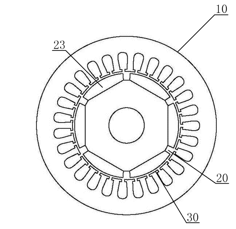
[0034] Please refer to Figure 5 , the present invention is a permanent magnet synchronous motor with magnetism gathering effect, which adopts a built-in tangential rotor magnetic circuit structure, including a stator 10 and a rotor 20, an air gap 30 is provided between the stator 10 and the rotor 20, and the stator 10 includes a stator core 11 and stator winding 12, the rotor 20 includes a rotor core 21, a rotating shaft 22 and a permanent magnet 23.

[0035] Please continue to refer Figure 5 , the stator 10 has nine slots, and the corresponding stator winding 12 can be further set as a fractional slot winding, which can increase the equivalent number of slots per pole and phase, thereby weakening the influence of higher harmonics; on the other hand, The significance of using the fractional slot winding is that it can effectively weaken th...


PUM


Abstract

The invention provides a permanent magnet synchronous machine (PMSM) possessing an assembled magnetic effect. The PMSM comprises a stator and a rotor. Air gaps exist between the stator and the rotor. The stator includes a stator core and a stator winding. The rotor includes a rotor core, a rotating shaft and permanent magnet steel. The stator winding is a centralized winding. The rotor is an eccentric rotor. Ends of the permanent magnet steel are directly connected with each other. The air gaps between the stator and the rotor are non-uniform air gaps. The invention has the following positive effects that: (1) distribution of air-gap flux density can be optimized through improving a rotor structure and the air gap flux can be very close to a sinusoidal waveform by using the non-uniform air gaps; (2) magnetic flux leakage on the ends can be effectively reduced because the ends of the permanent magnet steel are directly connected with each other, and simultaneously a magnetic isolation bushing is not needed to be installed on a rotating shaft side so that a requirement of a rotating shaft material can be reduced, wherein the rotating shaft can adopt a magnetic conductive material and / or a non magnetic conductive material.

Description

technical field [0001] The invention relates to an AC synchronous motor, in particular to a permanent magnet synchronous motor with magnetism gathering effect. Background technique [0002] Permanent Magnet Synchronous Machine (PMSM) has no excitation winding and excitation device, does not consume excitation power, and can also save slip rings and brushes, so compared with electric excitation motors, it has simple structure, reliable operation, High power density, low loss, flexible shape and size and other significant advantages, the application range is extremely wide. [0003] The traditional permanent magnet synchronous motor can be divided into surface type and built-in type according to the position of the permanent magnet on the rotor. The air gap between the stator and the rotor is uniform, and the stator winding adopts distributed winding to make the air gap magnetic flux of the motor better close to the sinusoidal distribution. [0004] attached figure 1 What i...

Claims


Application Information

Patent Timeline
Patent Type & Authority Applications(China)
IPC IPC(8): H02K21/14H02K1/27H02K1/16
Inventor 曹书豪赵朝会项峰陈垒李键张迪
Owner SHANGHAI DIANJI UNIV
Learn More