Supercharge Your Innovation With Domain-Expert AI Agents!

Shell and tube heat exchanger

A technology of shell-and-tube heat exchangers and coils, which is applied in the direction of heat exchanger types, heat exchanger shells, indirect heat exchangers, etc., and can solve problems such as low heat exchange efficiency, bulky volume, and bulky heat exchange equipment , to achieve the effect of improved heat transfer efficiency, broad application prospects and wide application value

Inactive Publication Date: 2013-01-30
BEIHANG UNIV
View PDF6 Cites 1 Cited by
  • Summary
  • Abstract
  • Description
  • Claims
  • Application Information

AI Technical Summary

Problems solved by technology

However, traditional shell-and-tube heat exchangers have disadvantages such as small heat transfer area and low heat transfer efficiency. The volume is huge and occupies a lot of land, and the resulting metal consumption per unit heat transfer area is also quite astonishing.
Due to the shortcomings of traditional shell-and-tube heat exchangers such as bulky size and high investment, their use in various thermal systems is limited

Method used


Image

  • Shell and tube heat exchanger
  • Shell and tube heat exchanger
  • Shell and tube heat exchanger

Examples


Embodiment

[0033] Take the 6+5 row coil tube bundle as an example.

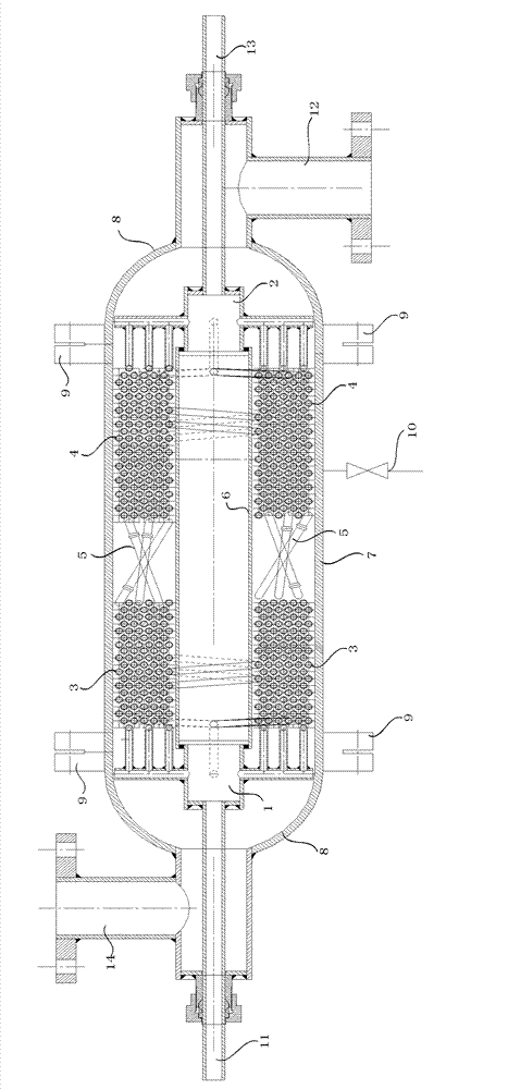
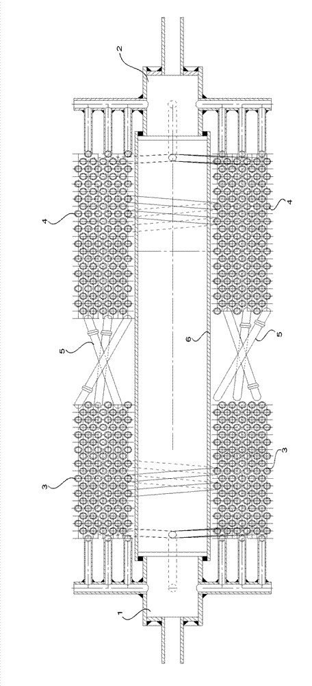
[0034] Such as Figure 5 As shown, the coiled pipes are divided into even rows and odd rows (that is, 6 rows and 5 rows, 11 rows in total), and are coiled alternately on the support pipe 6 in the middle. ( Figure 5 a in represents the distance between the support pipe 6 and the innermost coil)

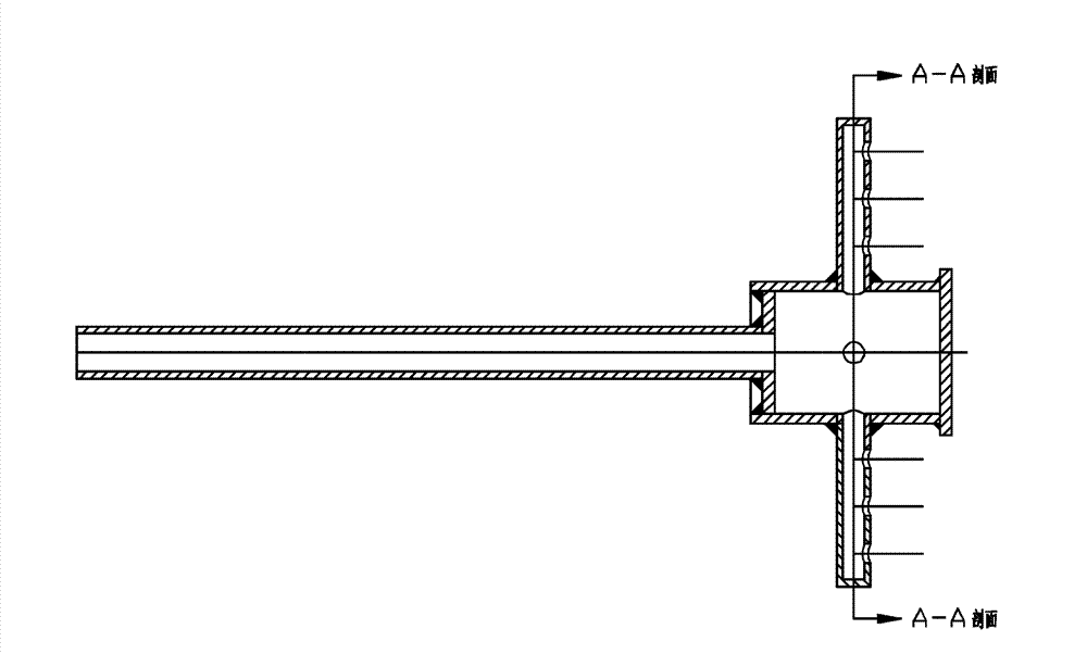
[0035] Inlet mixing chamber 1, outlet mixing chamber 2 such as image 3 , Figure 4As shown, for the flow in the pipe, a plurality of shunt pipes are arranged on the inlet mixing chamber 1 and the outlet mixing chamber 2, and circular ports are arranged on these shunt pipes to connect with the coil phase tube bundles respectively. image 3 In the example, four shunt pipes are set in the four directions of the inlet mixing chamber 1 and the outlet mixing chamber 2 respectively, as shown in Figure 4 As shown, three of the shunt pipes are provided with 3 circular ports, and the remaining one of the shunt pipes is provided wi...


PUM


Abstract

The invention discloses a shell and tube heat exchanger, which comprises an inlet mixing chamber, an outlet mixing chamber, a first group of coils, a second group of coils, a coil adapter area, a supporting tube, a cylinder, a drainage pipe, a tube pass medium inlet, a shell pass medium inlet, a tube pass medium outlet and a shell pass medium outlet, wherein the first group of coils and the second group of coils are wound on the supporting tube respectively; an outlet of the first group of coils is connected with an inlet of the second group of coils through the coil adapter area; front and rear parts of the supporting tube are connected with the inlet mixing chamber and the outlet mixing chamber; a shunt tube of the inlet mixing chamber is connected with an inlet of a tube bundle of the first group of coils; a shunt tube of the outlet mixing chamber is connected with an outlet of a tube bundle of the second group of coils; the cylinder is connected with seal heads to form a shell; the shell pass medium outlet is formed on a seal head positioned at the front end; the shell pass medium inlet is formed on a seal head positioned at the rear end; and the drainage pipe is connected to the cylinder. Compared with the heat exchange efficiency of a common shell and tube heat exchanger, the heat exchange efficiency of the heat exchanger is greatly improved.

Description

technical field [0001] The invention relates to a high-efficiency compact shell-and-tube heat exchanger suitable for combinations of various pressures and working fluids, and belongs to the technical field of heat exchangers. Background technique [0002] With the rapid development of global industrialization, the consumption of energy such as coal, oil, and natural gas continues to increase, and the global energy crisis is becoming more and more serious. Therefore, the development of new energy, waste heat recovery and energy-saving technology is particularly important. Designing heat exchangers with high heat transfer efficiency to reduce energy consumption and material consumption is not only a problem that must be solved in modernization development, but also the key to alleviating the energy shortage. From this point of view, research and development of enhanced heat transfer technology, effective measures to enhance heat transfer, increase heat transfer and reduce the...

Claims


Application Information

Patent Timeline
Patent Type & Authority Patents(China)
IPC IPC(8): F28D7/04F28F9/26
Inventor 徐国强杜发荣张传杰董苯思韩树军李婷婷闻洁王旻辉
Owner BEIHANG UNIV
Features
  • R&D
  • Intellectual Property
  • Life Sciences
  • Materials
  • Tech Scout
  • Unparalleled Data Quality
  • Higher Quality Content
  • 60% Fewer Hallucinations
Learn More