
Reflective star sensor light shield

A star sensor and hood technology, which is applied in the field of spacecraft optics, can solve the problems of suppression angle limitation, insufficient structural order, and difficulty in guaranteeing, etc., and achieve the effects of strong suppression ability, reduced size, and simple processing

Inactive Publication Date: 2011-11-16
BEIJING RES INST OF SPATIAL MECHANICAL & ELECTRICAL TECH
View PDF10 Cites 42 Cited by
  • Summary
  • Abstract
  • Description
  • Claims
  • Application Information

AI Technical Summary

Problems solved by technology

[0003] The existing star sensor shading cover, such as the patent "CN 1502524 A star sensor shading cover and its design method", adopts a two-stage shading cover, and the extinction part of both poles adopts a conical surface structure. At the same time, the secondary absorption cone black paint spraying is limited by the existing technical level, so that the effect of suppressing strong stray light outside the field of view is greatly reduced, and the ideal effect cannot be achieved.
The light hoods reported in other public documents all adopt a two-stage light hood with a cylindrical light-blocking ring structure, which has a large volume and weight, and it is difficult to machine and spray black paint, and the ability to suppress strong stray light outside the field of view is relatively poor. Difficult to guarantee
[0004] The existing straight barrel-type hoods cannot meet the requirements of such a high suppression ability; for example, patents CN201255802, CN201322836, etc., cannot meet the suppression requirements of strong light sources outside the field of view, and the volume and weight are relatively large

Method used


Image

  • Reflective star sensor light shield
  • Reflective star sensor light shield
  • Reflective star sensor light shield

Examples


Embodiment Construction

[0021] The present invention will be further described below in conjunction with accompanying drawing.

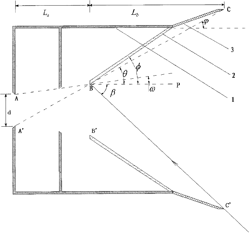
[0022] Such as figure 1 Shown is the basic form of the shading cover of the present invention, including a primary shading cover 1 , a secondary shading cover 2 and a tertiary shading cover 3 . The front end of the third-level light shield 3 is close to the light entrance, and the front ends of the first-level light shield 1 and the second-level light shield 2 are respectively connected with the rear ends of the third-level light shield 3 .

[0023] The third-level light shield 3 and the second-level light-shield 2 are thin-walled conical barrel structures, and the opening angle of the third-level light-shielding cover 3 is smaller than that of the second-level light-shielding cover 2 . The inner walls of the two are processed to a smooth and clean surface with high precision, and are sprayed with black paint or black film with high reflectivity and low scattering rate. I...


PUM


Abstract

A reflective star sensor light shield comprises three thin-wall cone barrels, wherein the three thin-wall cone barrels are successively connected. Inner walls of two cone barrels which are far from a lens are smooth clean surfaces and are sprayed with black paint or black films with high reflectivity and a low scattering rate. The inner wall of the cone barrel which is close to the lens is a baffle vane or a barrel type structure of eliminating veiling glare threads and is sprayed with black paint or black films with low reflectivity and the low scattering rate. The whole light shield can possess a optimal length through setting an algebraic relation of cone angles of each cone barrel. The reflective star sensor light shield of the invention has a short length and light weight, and is convenient for processing and manufacturing. The reflective star sensor light shield possesses strong inhibition capability for stray light, such as sunlight and ground gas light, which is a strong light source out of field of view. The invention can be used for the star sensor to shade light and be used for optical remote sensors to explore deep space, such as a star camera and the like.

Description

technical field [0001] The invention belongs to the technical field of spacecraft optics, in particular to a reflective shading cover for a star sensor. Background technique [0002] The star sensor hood is mainly to suppress stray light such as sunlight, earth atmosphere light and moon light outside the field of view. Compared with the brightness of the imaging target star, the brightness of these stray light sources is several orders of magnitude or even tens of orders of magnitude stronger, so the star sensor must have excellent suppression ability, so that the strong stray light outside the field of view on the image plane After many times of attenuation, it falls below the brightness of the imaging target. [0003] The existing star sensor shading cover, such as the patent "CN 1502524 A star sensor shading cover and its design method", adopts a two-stage shading cover, and the extinction part of both poles adopts a conical surface structure. At the same time, the seco...

Claims


Application Information

Patent Timeline
Patent Type & Authority Applications(China)
IPC IPC(8): G03B11/02B64G1/66B64D47/08
Inventor 廖志波焦文春伏瑞敏宗肖颖杜建祥
Owner BEIJING RES INST OF SPATIAL MECHANICAL & ELECTRICAL TECH
Learn More