
Modular selective catalytic reduction (SCR) denitration rectification grating device

A rectifying grid and modular technology, applied in the field of flue gas denitrification, can solve the problems of increased installation and system operation costs, high requirements for catalyst flow field distribution, difficulty in manufacturing and installing deflectors, etc., to achieve simple and fast production and installation , Inexpensive materials, no need for repair and maintenance

Active Publication Date: 2011-11-16
SHANGHAI LONGKING ENVIRONMENTAL PROTECTION
View PDF3 Cites 6 Cited by
  • Summary
  • Abstract
  • Description
  • Claims
  • Application Information

AI Technical Summary

Problems solved by technology

Generally, a large number of deflectors of different shapes are arranged in the SCR denitrification inlet flue and the front end of the reactor to make the flow distribution of flue gas and dust meet the required requirements. However, from the experience of installation and operation at home and abroad, due to the The cross-section is large, and the catalyst has high requirements on the distribution of the flow field. It is very difficult to manufacture and install various deflectors with strange shapes. At the same time, the dust in the flue gas is easy to accumulate on the surface of the deflector, thereby increasing the installation and system operation costs. The denitrification performance is also greatly reduced

Method used


Image

  • Modular selective catalytic reduction (SCR) denitration rectification grating device
  • Modular selective catalytic reduction (SCR) denitration rectification grating device
  • Modular selective catalytic reduction (SCR) denitration rectification grating device

Examples


Embodiment Construction

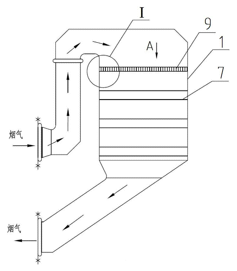
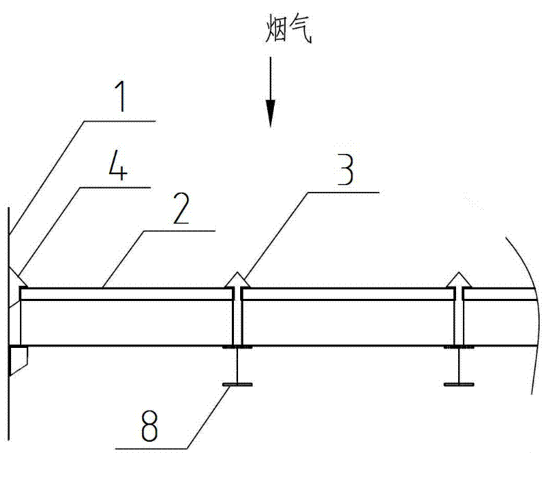
[0017] figure 1 It is a schematic diagram of the installation and use position of the present invention, showing that the modularized SCR denitrification rectifying grid device is placed on the support beam 8 above the first catalytic layer 7 in the SCR reactor 1 ( figure 2 ), located at the front end 9 of the SCR reactor 1, so that after the flue gas passes through the modular SCR denitrification rectifying grille device, the flow direction and flow velocity distribution of the dust-laden flue gas achieve an ideal effect.

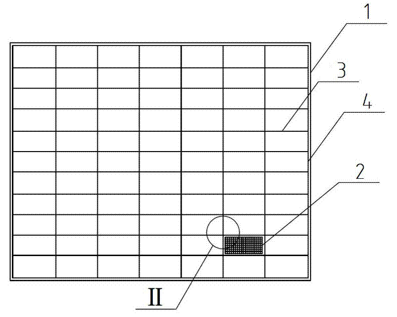
[0018] The schematic diagram of enlarged structure of the present invention is shown in Figure 2 ~ Figure 4 , it can be seen from the figure that the longitudinal grid and the horizontal grid of the rectification module are cross-connected and fixed to each other, forming a grid structure in which a plurality of hollow thin-walled tubes 6 are neatly arranged and connected to each other. The rectification module 2 is surrounded by a ring Surrounding the ...


PUM


Abstract

The invention belongs to the technical field of smoke denitration (namely NOx removal), and relates to a modular selective catalytic reduction (SCR) denitration rectification grating device, which is characterized in that longitudinal gratings and transverse gratings of rectification modules are in crossed connection mutually to be fixed and have a grid-shaped structure in which a plurality of hollow thin-wall pipes are arranged and connected regularly and mutually, and the axial directions of the hollow thin-wall pipes are consistent with the height directions of the rectification modules; asealing element is divided into an internal sealing element and an external sealing element; the internal sealing element is positioned in gaps among the rectification modules; and the external sealing element is positioned between the rectification modules and the inner wall of an SCR reactor. The invention has the advantages that after smoke passes through the modular SCR denitration rectification grating device, the flow direction and flow speed distribution of the smoke mingled with dust achieve an ideal effect; meanwhile, the dust in the smoke cannot be accumulated on the rectification grating device; and the rectification grating device is easy to manufacture and low in comprehensive investment cost, and is not needed to be overhauled or maintained, the cost of materials is low, andthe flow field performance of the smoke is improved, so the NOx removal performance of the system is improved.

Description

technical field [0001] The invention belongs to the technical field of flue gas denitrification (that is, NOx removal), and relates to a modular SCR denitrification rectifying grid device applied in an SCR denitrification system to uniformly distribute flue gas and dust before entering a catalyst layer. Background technique [0002] NOx (nitrogen oxides) is one of the main air pollutants. Nitrogen oxides are produced by the combustion of fossil fuels and air at high temperatures, including nitric oxide (NO), nitrogen dioxide (NO 2 ) and nitrous oxide (N 2 O), and NxOy. SCR (Selective Catalytic Reduction, SCR for short) denitrification technology is a certain concentration of ammonia (NH 3 ) is sprayed into the flue gas and mixed with the flue gas, and the NH 3 React with NOx to generate non-toxic and harmless N 2 and water to achieve the purpose of removing NOx. Since the denitration reaction occurs instantaneously when the flue gas contacts the surface of the solid cat...

Claims


Application Information

Patent Timeline
Patent Type & Authority Applications(China)
IPC IPC(8): B01D53/90B01D53/56
Inventor 陈海峰吴文辉刘晓琴方辉
Owner SHANGHAI LONGKING ENVIRONMENTAL PROTECTION
Learn More