
Heat exchange pipe and on-line pipe-making processing technique thereof

A processing technology and technology of heat exchange tubes, applied in the field of metal tube processing, can solve problems such as heat exchange area, heat exchange efficiency is difficult to be greatly improved, cold processing technology is difficult to guarantee the quality of finished products, heat exchange tube finished specifications, length limitations, etc. , to achieve the effect of saving off-line heat treatment equipment, low cost of pipe making, and reduction of secondary processing processes

Inactive Publication Date: 2011-11-02
SHANGHAI KEMI STEEL TUBE
View PDF5 Cites 3 Cited by
  • Summary
  • Abstract
  • Description
  • Claims
  • Application Information

AI Technical Summary

Problems solved by technology

[0011] 1. Due to the specifications of cold processing equipment, the finished heat exchange tubes are greatly limited in terms of specifications and length;
[0012] 2. Due to the cold processing steps, the loss of raw materials is relatively large;
[0013] 3. Due to the complex cold processing process, the processing accuracy of the product is uneven;
[0014] 4. It is difficult to guarantee the quality of the finished product by the inspection method and inspection method of the cold processing process;
[0015] 5. Limited by the processing technology, the tube making efficiency is not high;
[0016] 6. Most of these four types of heat exchange tubes have special shapes, which bring a lot of inconvenience to the production of heat exchanger equipment such as the disposal of bellows and baffles of outer grooved tubes;
[0017] 7. These four types of heat exchange tubes have been cold-worked, and there are residual stresses on the tube body, which will form turbulent flow when the medium passes through, which strengthens the local corrosion of the heat exchange tubes, so it has a certain impact on the service life of the heat exchanger equipment. negative impact
[0018] Due to the above reasons, the heat exchange tubes in the prior art have entered a technical bottleneck, and it is difficult to greatly increase the heat exchange area and heat exchange efficiency, which restricts the development of heat exchangers and is difficult to meet the needs of the market

Method used


Image

  • Heat exchange pipe and on-line pipe-making processing technique thereof
  • Heat exchange pipe and on-line pipe-making processing technique thereof
  • Heat exchange pipe and on-line pipe-making processing technique thereof

Examples


Embodiment 1

[0073] The heat exchange tube of the present invention is a metal tube with a certain length, mainly comprising a metal outer tube 1 and an inner tube 2 arranged inside the outer tube 1 , the two are closely matched and fixed together.

[0074] Such as Figure 5 As shown, in this embodiment, the outer pipe 1 is a metal welded pipe, such as austenitic stainless steel welded pipe, carbon steel welded pipe, titanium and titanium alloy welded pipe, nickel and nickel alloy welded pipe, or austenitic-ferrite dual phase steel welded pipe etc. The inner and outer surfaces of the outer tube 1 are both smooth surfaces.

[0075] The inside of the outer tube 1 forms a medium channel through which the heat exchange medium circulates, and an inner tube 2 is also provided. The inner tube 2 is used as a heat exchange component in the outer tube 1, and together with the outer tube 1 constitutes the heat exchange tube of the present invention. In this embodiment, the inner pipe 2 is also a m...

Embodiment 2

[0094] Such as Figure 6 As shown, the structure of the heat exchange tube of this embodiment is basically the same as that of the above-mentioned embodiments, and both include an outer tube 1 and an inner tube 2 used as a heat exchange component. The difference is that the outer surface of the inner tube 2 is spiral.

[0095] In other embodiments, T-shaped grooves, screw grooves, etc. are provided on the outer surface of the inner tube 2 to achieve basically the same technical effect.

Embodiment 3

[0097] The structure of this embodiment is basically the same as that of Embodiment 1, including an outer tube 1 and an inner tube 2. The difference is that the cross-sectional shape of the inner tube 2 is triangular, and three direct heat exchange zones 31 are formed in the outer tube 1. and an indirect heat exchange zone 32.

[0098] In addition, at least one through hole 23 is provided on the tube wall of the inner tube 2 . These through holes 23 may be O-shaped holes or star-shaped holes or polygonal holes or other special-shaped holes.

[0099] Preferably, see Figure 7 , Figure 8 Shown is the side view structure of the inner tube 2 in this embodiment, and a plurality of through holes 23 are distributed in an array on the tube wall of the inner tube 2 .

[0100] In other embodiments, the cross section of the inner tube 2 can have various forms. Such as Figure 9A , Figure 9B , Figure 9C , Figure 9D , Figure 9E , Figure 9F , Figure 9G , Figure 9H , Figu...


PUM


Abstract

The invention discloses a heat exchange pipe, which comprises an outer pipe at least. The interior of the outer pipe serves as a medium passage. A heat exchange element is configured inside the medium passage. The heat exchange element divides the medium passage into a direct heat exchange zone which exchange heat with the outer pipe and an indirect heat exchange zone which exchange heat with the heat exchange element. The heat exchange medium inside the indirect heat exchange zone exchanges heat with the heat exchange medium inside the direct heat exchange zone via the heat exchange element. In addition, the invention provides an on-line pipe-making processing technique of the pipe, which is adopted to overlap the outer pipe with the heat exchange element by means of an on-line welding technique. Because the heat exchange element is configured inside the outer pipe, the heat exchange area of the heat exchange pipe provided by the invention is increased, which greatly improves the heat exchange efficiency of the indirect heat exchange zone so that the heat exchange pipe provided by the invention is superior to the current heat exchange pipes in terms of the overall heat exchange efficiency. In addition, the invention has low cost and is convenient for manufacturing, and the heat exchange pipe provided by the invention can be applied to high-efficiency heat exchangers or heat exchanging equipment of multiple industries like petroleum, chemicals, fertilizer, boilers, pharmacy, foodstuff, electric power, nuclear power, environmental protection, heat supply and the like.

Description

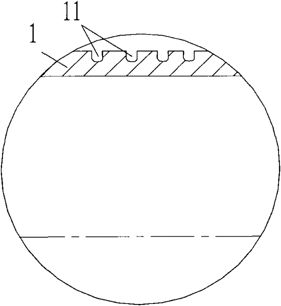
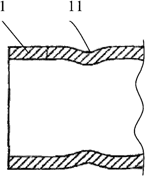
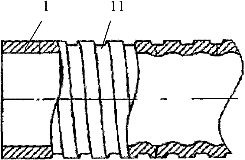
technical field [0001] The invention relates to the technical field of metal tube processing, in particular to a heat exchange tube used for heat exchange equipment such as a heat exchanger. The present invention also relates to the processing technology of the aforementioned heat exchange tube. Background technique [0002] According to GB / T24590-2009 "Heat Exchange Tubes for High Efficiency Heat Exchangers" standard, my country's current high-efficiency heat exchange tubes for heat exchangers are divided into four types, namely T-groove tubes, corrugated tubes, internal wave and external threaded tubes, Inner groove tube. The biggest thing they have in common is that they are all heat exchange tubes manufactured and processed on metal base tubes (straight tubes) by cold working process. [0003] Such as figure 1 As shown, in the T-shaped groove pipe in the prior art, dense spiral T-shaped grooves 11 are formed on the outer wall of the metal base pipe 1 by cold working. ...

Claims


Application Information

Patent Timeline
Patent Type & Authority Applications(China)
IPC IPC(8): F28F1/00F28F1/02F28F1/04B21D53/06
CPCY02P20/10
Inventor 孔祥锋
Owner SHANGHAI KEMI STEEL TUBE
Learn More