
Maximum torque control method for salient-pole permanent-magnet synchronous motor

A technology of permanent magnet synchronous motor and maximum torque, which is applied in the field of current generation of d-axis current command id*, salient pole permanent magnet synchronous motor vector control, q-axis current command iq*, and can solve the problem of maximum deviation of current operating point Torque control, complex generation process, no comprehensive consideration, etc.

Inactive Publication Date: 2011-10-19
西安绿港科技发展有限公司
View PDF7 Cites 25 Cited by
  • Summary
  • Abstract
  • Description
  • Claims
  • Application Information

AI Technical Summary

Problems solved by technology

[0006] The defect of the method described in CN101626216A is that in order to generate the optimal vector control current value under the specific torque, it is necessary to implement the motor to measure the current under various torque conditions to determine the most suitable d-axis current i d , q-axis current i q operation, the generation process is complex
The field weakening module is introduced in the adjustment process above the base speed, and the direct axis current command i d * compensating without taking into account i q This will inevitably cause the current operating point to deviate from the requirement of maximum torque control

Method used


Image

  • Maximum torque control method for salient-pole permanent-magnet synchronous motor
  • Maximum torque control method for salient-pole permanent-magnet synchronous motor
  • Maximum torque control method for salient-pole permanent-magnet synchronous motor

Examples


Embodiment Construction

[0040] Now in conjunction with embodiment, accompanying drawing, the present invention will be further described:

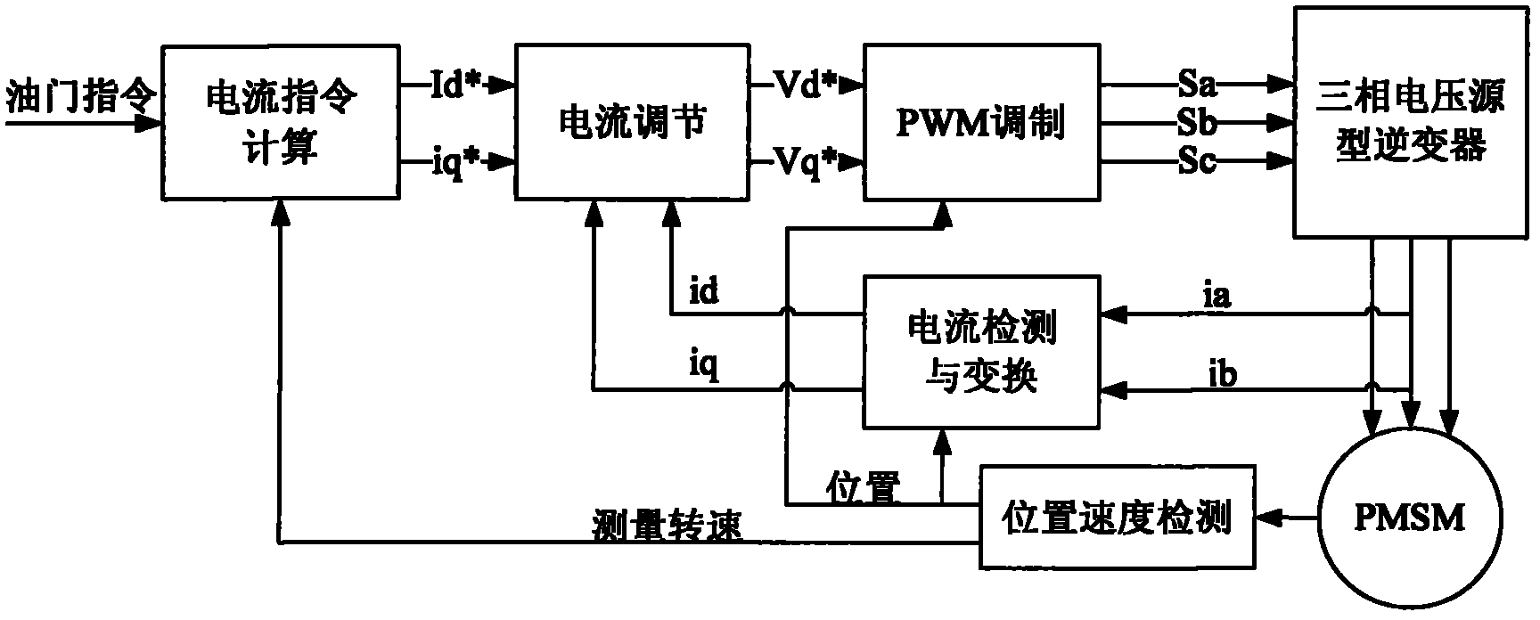
[0041] The vector control system structure of the embodiment of the present invention is as follows figure 1As shown, it includes a permanent magnet synchronous motor (PMSM), a three-phase voltage source inverter, a PWM modulation unit, a current detection and conversion unit, a current regulation unit, a current calculation unit and a position speed detection unit.

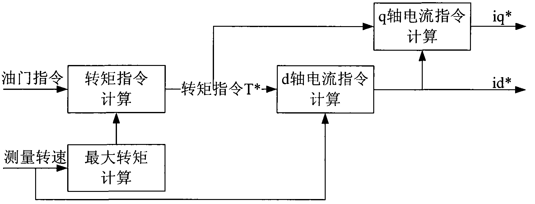
[0042] figure 2 shown as figure 1 A detailed block diagram of the medium current command calculation unit, including a torque command calculation unit, a maximum torque calculation unit, a d-axis current command calculation unit, and a q-axis current command calculation unit.

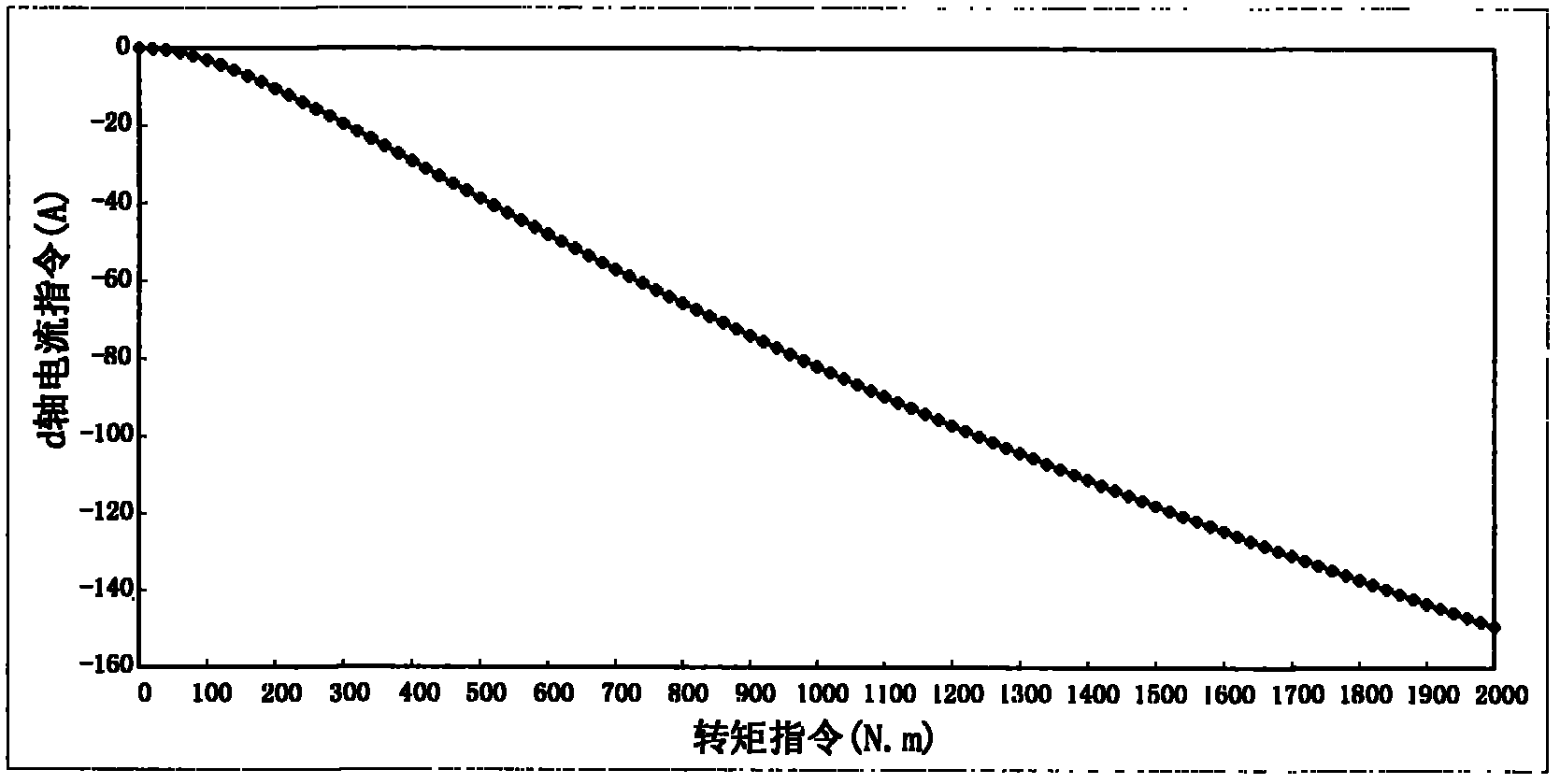
[0043] In order to verify the method of the present invention, a 130kW permanent magnet synchronous motor is used for simulation verification. The motor parameters are: bus voltage 540V, number of pole pairs p=2, winding ...


PUM


Abstract

The invention provides a maximum torque control method for a salient-pole permanent-magnet synchronous motor, which is characterized in that vector control on the motor is carried out by a d-axis current instruction id* and a q-axis current instruction iq* under the synchronous rotation coordinate system of a rotor, thus realizing the aim of outputting maximum torque of the motor. Compared with the traditional control method, the maximum torque control method has the advantages of 1) offline calculating current instruction values, controlling in real time by only searching; greatly simplifying real-time operation; and reducing the requirement on the processing capability of a controller; 2) combining a table searching of d-axis current instruction with the precise calculation of q-axis current instruction, thus reducing the error caused by the table searching; and improving torque control precision.

Description

technical field [0001] The invention relates to a vector control method of a salient pole permanent magnet synchronous motor, in particular to a d-axis current command i capable of realizing maximum torque control d * , q-axis current command i q * The invention discloses a method for generating electric current, which belongs to the technical field of AC motor transmission. Background technique [0002] Permanent magnet synchronous motors are widely used in electric traction systems, including high-speed railway electric drive systems, automobile electric drive systems, elevators, etc. Toothless traction system, etc. [0003] The salient pole permanent magnet synchronous motor adopts the structure of the permanent magnet embedded in the rotor, which has a larger salient pole ratio than the surface mount type, and can generate large reluctance torque and high-efficiency output torque. The core of the vector control of the salient pole permanent magnet synchronous motor ...

Claims


Application Information

Patent Timeline
IPC IPC(8): H02P21/14H02P21/20
Inventor 骆光照杨南方刘卫国窦满峰
Owner 西安绿港科技发展有限公司
Learn More