
Copper smelting device and process

A copper smelting device and process technology, applied in the field of copper smelting devices, can solve the problems of low cost and achieve the effects of low air leakage rate, less heat, and strong ability to process mineral materials

Inactive Publication Date: 2011-09-14
DONGYING LUFANG METAL MATERIAL
View PDF2 Cites 35 Cited by
  • Summary
  • Abstract
  • Description
  • Claims
  • Application Information

AI Technical Summary

Problems solved by technology

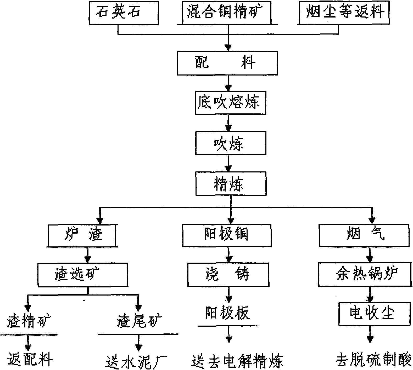
[0004] Aiming at the defects and deficiencies of the above smelting process, the present invention provides a copper smelting device and process that can simultaneously complete the three processes of smelting, blowing and refining in one furnace, which can not only solve the problem of SO2 low-altitude pollution, but also make the operation The environment is greatly improved, and the utilization rate of sulfur and heat energy is significantly improved, which further improves the economic benefits. At the same time, it is more advanced than the existing continuous copper smelting process, the process is shorter, the investment is less, the cost is lower, the comprehensive energy consumption is lower, and the recycling Higher efficiency and better comprehensive utilization

Method used


Image

  • Copper smelting device and process
  • Copper smelting device and process
  • Copper smelting device and process

Examples


Embodiment

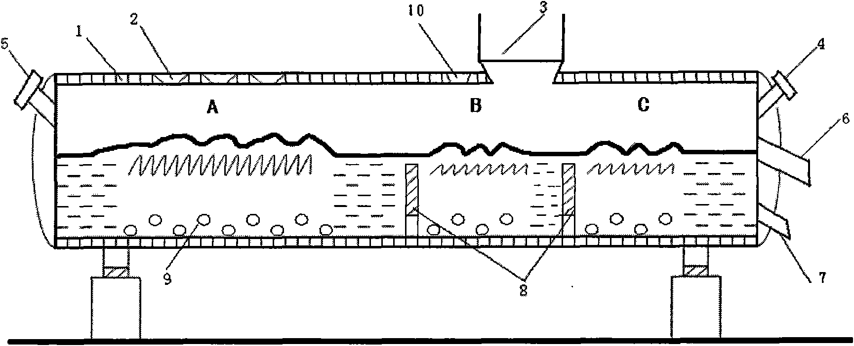
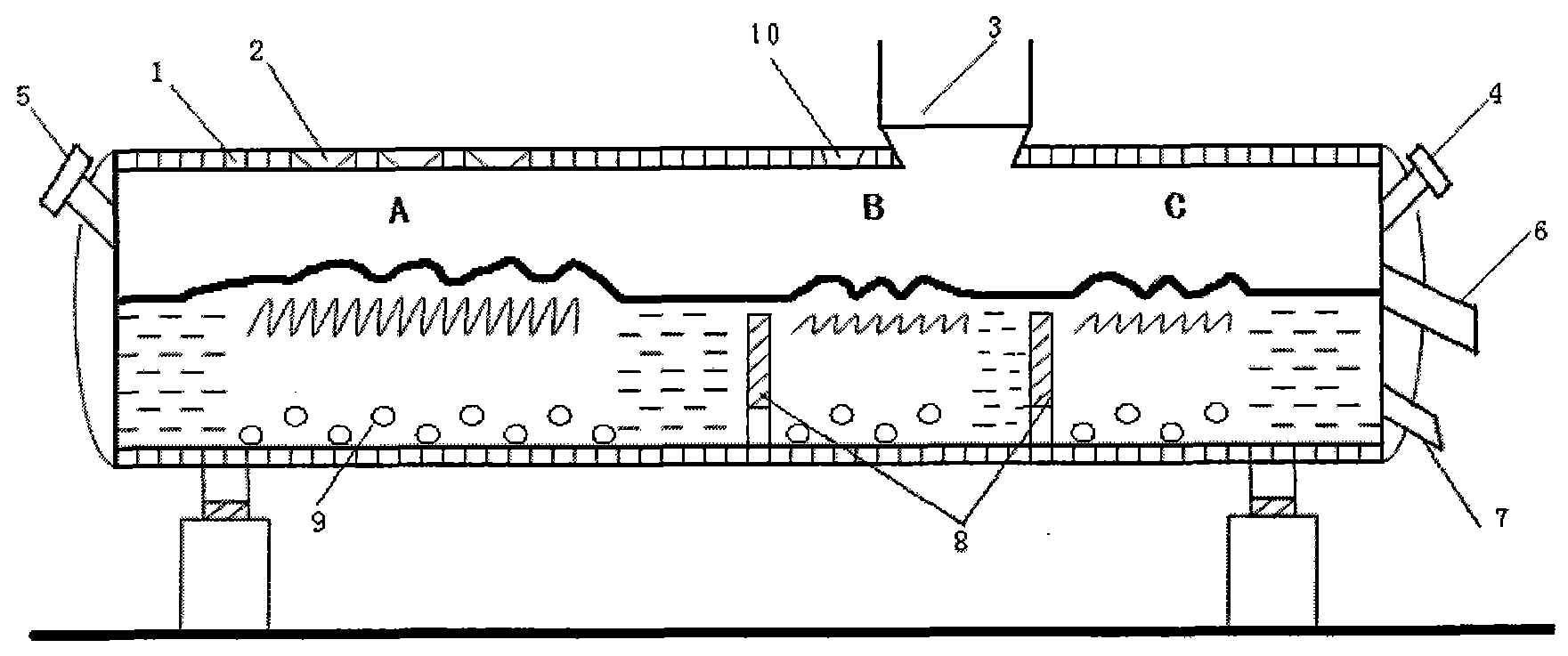
[0036] Example: The furnace is divided into three zones by a retaining wall, namely smelting zone A, blowing zone B, and refining zone C. The lengths of the three zones are 15m, 8m, and 8m respectively, and the inner diameter of the furnace is 4.8m. Install two rows of staggered arrangements at the bottom of smelting area A, with an interval of 1.1m, and 9 spray guns 9 at angles of 17° and 22° to the vertical; install two rows of staggered arrangements at the bottom of blowing area B with an interval of 1.1m , 5 spray guns 9 at angles of 35° and 40° to the vertical; two rows of staggered arrangements, 1.1m apart, and 5 spray guns 9 at angles of 45° and 50° to the vertical are respectively installed at the bottom of the refining area C.

[0037] After the mixed copper concentrate is mixed with flux and returned dust, it is fed into the furnace from the feeding port 2 on the upper part of the smelting zone A, and 75% oxygen-enriched air is injected into the smelting furnace from ...


PUM


Abstract

The invention provides a copper smelting device and a copper smelting process. In the device, a shell of a rotary horizontal type cylindrical furnace body is made of a steel plate; an inner liner is made of a refractory material; the furnace body passes through two supporting rings and is supported on a foundation through four supporting rollers; one side of the furnace body is provided with a transmission mechanism; a motor is used for driving a speed reducer to drive the furnace body to rotate along a central shaft through a gear and a gear ring on a cylinder; the furnace body is partitioned into a smelting area, a blowing area and a refining area by a refractory brick retaining wall; a gap is formed at the bottom of the retaining wall; the bottoms of all areas are provided with a spray gun respectively; a charging hole is formed above the smelting area; a flue hole and a fluxing agent hole are formed above the blowing area; a main burner nozzle and an auxiliary burner nozzle are arranged on the shell of the furnace body end close to the two sides of the smelting area and the refining area respectively; and a slagging hole and a copper discharging hole are formed on the shell of the furnace body end on one side of the auxiliary burner nozzle. The device has a simple structure, a reasonable design and extremely good popularization value and application value and is energy-saving and environment-friendly.

Description

Technical field [0001] The invention belongs to the field of nonferrous metallurgy, and relates to a copper smelting device and a process capable of processing polymetallic complex ores and precious metal associated ores. Background technique [0002] At present, as far as the smelting process is concerned, the pyrometallurgy of copper has been used in industrial production: flash furnace smelting, Noranda smelting, Osmelt smelting, Aisa smelting, silver smelting, bottom blowing smelting and traditional Blast furnace smelting, electric furnace smelting, reverberatory furnace smelting, etc. The above smelting methods are all relatively advanced smelting processes adopted in the world today, except for the last three traditional methods which are difficult to meet the environmental protection standards. As far as copper blowing is concerned, more than 90% of the world today uses PS converters. As far as copper refining is concerned, most of them use rotary furnace refining, ...

Claims


Application Information

Patent Timeline
IPC IPC(8): C22B15/00
Inventor 崔志祥
Owner DONGYING LUFANG METAL MATERIAL
Learn More