
Mounting for a pipeline

A technology for fluid pipelines and components, applied in the field of connecting devices on motor vehicle components, can solve problems such as production costs

Active Publication Date: 2014-02-26
CONTITECH TECHNO CHEM
View PDF6 Cites 0 Cited by
  • Summary
  • Abstract
  • Description
  • Claims
  • Application Information

AI Technical Summary

Problems solved by technology

[0004] It is advantageous here that these measures incur costs, for example due to the material use of the solder resist and / or the time required for this

Method used


Image

  • Mounting for a pipeline
  • Mounting for a pipeline

Examples


Embodiment Construction

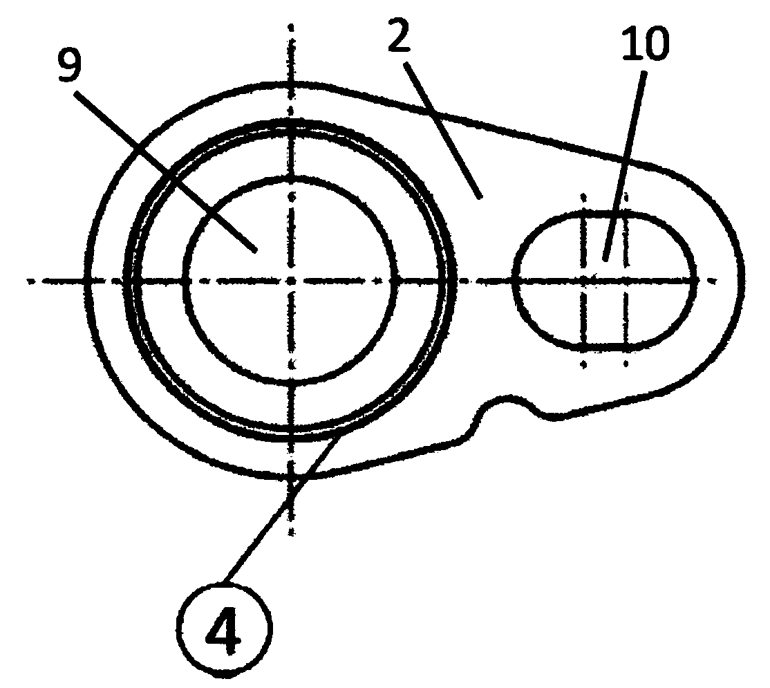
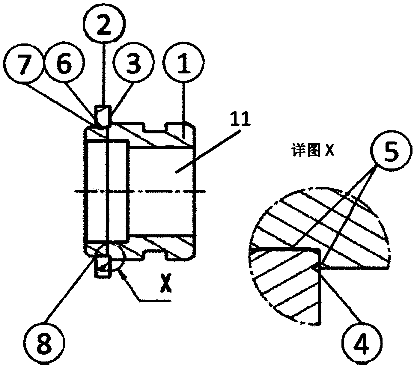
[0016] figure 1 A diagrammatic plan view of one flange 2 is shown. Flange 2 has a stub 1 for receiving (see figure 2 ) of a first opening 9 . Correspondingly, the inner diameter of the first opening 9 (bore 6, see figure 2 ) at least radially slightly larger than (connection diameter 7, see figure 2 ) the outer diameter of the stud 1 in the region 3 in which the flange 2 is to be inserted onto the stud 1 (insertion region 3).

[0017] Furthermore, the flange 2 has a second opening 10 . Through this second opening 10 the flange 2 and thus also the entire mounting device can be screwed onto a component, for example, in order to produce a fixed and fluid-tight connection between the component and a fluid line.

[0018] According to the invention, the flange 2 has a recess 4 which is preferably configured as a relief groove 4 . Said groove 4 extends radially on one face of the flange 2 around the first opening 9 . The groove 4 is configured and arranged on the flange 2 i...


PUM


Abstract

A connecting arrangement connects an end of a fluid conduit to an assembly. The connecting arrangement includes a stub (1) having a flow opening (11) for receiving the fluid conduit at one end of the flow opening (11) as well as a flange (2) having a first opening (9) for receiving the stub (1) and a second opening (10) for fastening to the assembly. The stub (1) is inserted into the first opening (9) and connected to the flange (2) in a material-to-material manner. The flange (2) has in the region of the connection a groove (4) that extends in a circumferential direction.

Description

technical field [0001] The invention relates to a connection device according to the preamble of claim 1 for connecting one end of a fluid line to a component, in particular a motor vehicle component, which has a through-flow opening and has a a fluid. Background technique [0002] In a motor vehicle, pipes, hoses and lines are used to direct different fluids between the individual components of the engine. To connect the lines to these components, connection arrangements are used which may for example have a stub and a flange connected to each other in a material-to-material manner, for example by a soldered connection. [0003] A general requirement for this type of connection arrangement is that the stub and flange insertion areas be free of solder residues or solder accumulations. This is usually avoided by using special solder resists or complex structures that avoid the transfer from the stub to the flange in the insertion area. Another costly method is to remove so...

Claims


Application Information

Patent Timeline
Patent Type & Authority Applications(China)
IPC IPC(8): F16L23/026
CPCF16L23/026F16L13/08
Inventor 马库斯·派于斯特于尔根·福伊克米夏埃尔·哈恩
Owner CONTITECH TECHNO CHEM
Learn More