


Quick Research
Generate reliable direction feasibility study reports for your R&D in just a few steps.

Technical Q&A
Discover and master advanced knowledge NOW. Basics, ideas, possibilities, all at once.

Find Solutions
As an expert in R&D theories, this can generate solutions to your technical problems instantly.

Evaluate Feasibility
Analyze your overall solution with one click, know your potential R&D risks in advance.

Monitor Landscape
Get weekly tech updates, stay abreast of the latest tech innovations and key insights.
Saving type ink jet printing process for solar cell grid lines
A solar cell, inkjet printing technology, applied in the printing process, printing and printing of special varieties of printed matter, can solve the problems of waste of paste, no cost advantage, etc., to save paste, reduce costs, and meet the requirements of electrical conductivity. effect of sexual demands
- Summary
- Abstract
- Description
- Claims
- Application Information
AI Technical Summary
Problems solved by technology
Method used
Image

Examples
Embodiment Construction
[0016] The present invention will be further described below in conjunction with accompanying drawing and specific embodiment:
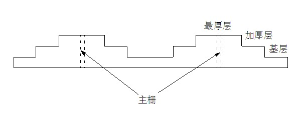
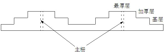
[0017] As shown in the accompanying drawing: a kind of energy-saving inkjet printing process of grid lines of solar cells, the process includes the following steps:
[0018] 1. Prepare the inkjet printing equipment and make the silver-containing paste into ink;
[0019] 2. Inkjet printing along the route of the fine grid line, the amount of paste sprayed by the nozzle is proportional to the cross-sectional area of the fine grid line, and the amount of paste printed at both ends of the fine grid line is smaller than the amount of paste printed near the main grid line , so that the cross-sectional area of both ends of the thin grid line is smaller than the cross-sectional area of the thin grid line close to the busbar, so as to match cells with different requirements.
[0020] In the second step, the cross-sectional area of the thin grid is ch...
PUM
 Abstract
Description
Claims
Application Information
 - R&D Engineer
- R&D Manager
- IP Professional
- Industry Leading Data Capabilities
- Powerful AI technology
- Patent DNA Extraction
Browse by: Latest US Patents, China's latest patents, Technical Efficacy Thesaurus, Application Domain, Technology Topic, Popular Technical Reports.
© 2024 PatSnap. All rights reserved.Legal|Privacy policy|Modern Slavery Act Transparency Statement|Sitemap|About US| Contact US: help@patsnap.com