High-temperature crude synthesis gas chilling device

A crude synthesis gas and chilling technology, which is applied in the manufacture of combustible gas, climate sustainability, petroleum industry, etc., can solve the problems of high power consumption of synthesis gas cycle compression, poor chilling effect, and large chilled gas volume, etc. To achieve the effect of shortened residence time, simple structure and high chilling efficiency

Active Publication Date: 2011-08-03
WISON ENG
View PDF5 Cites 18 Cited by
  • Summary
  • Abstract
  • Description
  • Claims
  • Application Information

AI Technical Summary

Problems solved by technology

The applicant proposed a synthesis gas preparation and heat recovery method in the patent CN200710175473.5. In the method, the high-temperature synthesis gas and the slag droplets carried by it need to be quenched to the temperature range required by the process. The applicant In patents CN200910047706, CN201020567950, CN201020607955, and CN201020607531, a new coal gasification equipment is proposed, which is used to realize coal-to-synthesis gas, partial quenching of syngas and first-stage heat recovery in the method described in patent CN200710175473.5 Steps, in the aforementioned five patents, it is necessary to chill the high-temperature crude syngas and the slag droplets carried by it to a specific temperature range. It is easy to burn out the chilling ring and the downcomer. If Shell’s chilling tube structure is used, the amount of chilling gas required is large, the power consumption of syngas cycle compression is large, and the chilling effect is not good. In order to overcome the existing syngas chilling device The present invention provides a chilling device for chilling the high-temperature crude gas to a specific temperature range, which can quickly, efficiently, and uniformly chill the high-temperature syngas and the slag droplets carried by it to the temperature range set by the process

Method used


Image

  • High-temperature crude synthesis gas chilling device
  • High-temperature crude synthesis gas chilling device
  • High-temperature crude synthesis gas chilling device

Examples


Embodiment 1

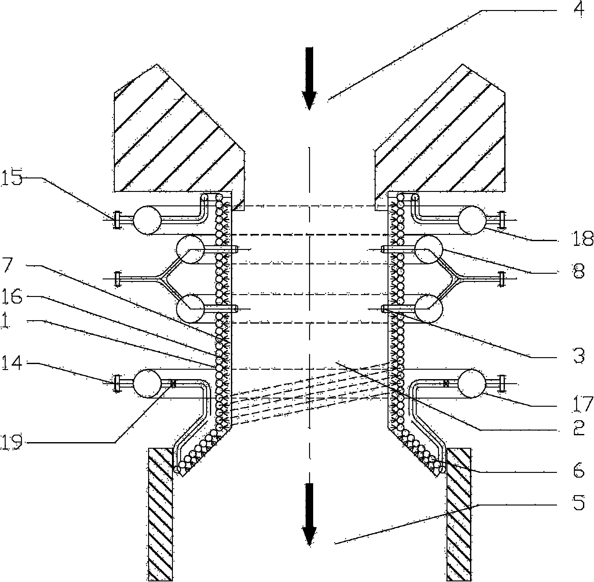
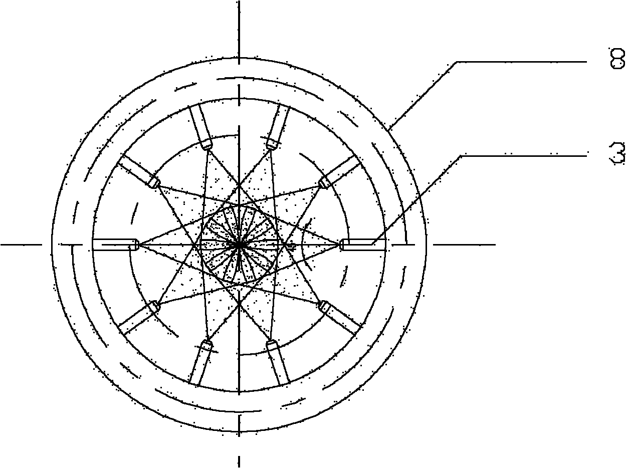
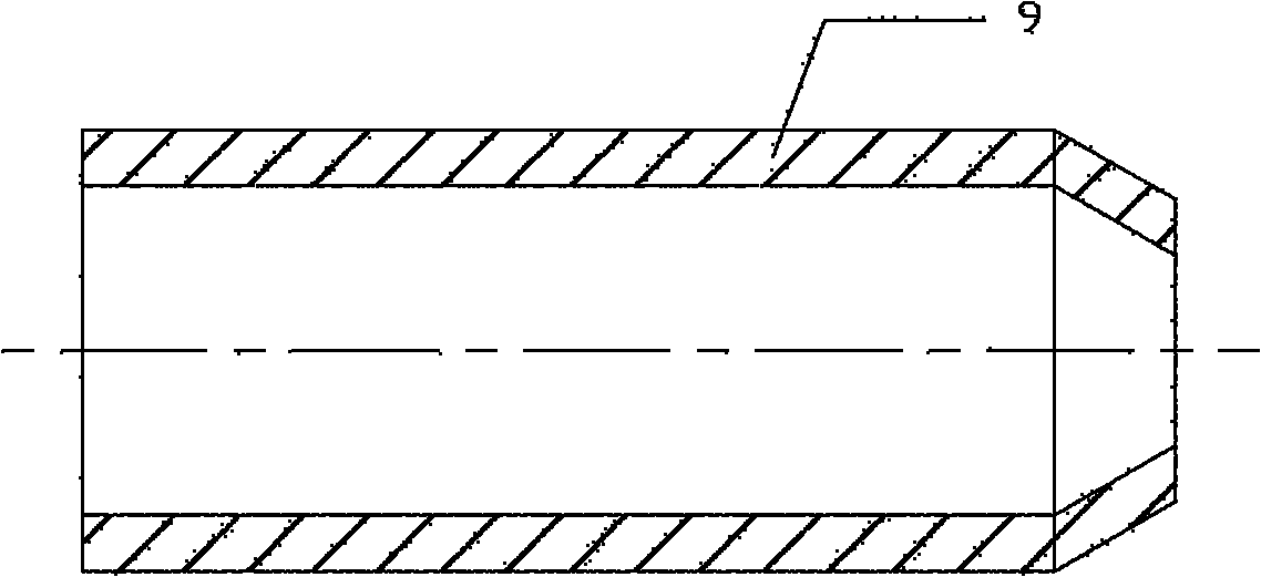
[0026] Such as figure 1 As shown, a chiller 1 for high-temperature crude syngas includes a gas flow channel 2 of the chiller 1 and an atomizing nozzle 3 installed on the side wall of the gas flow channel 2, and the gas flow channel 2 is used to connect the gasifier The reaction chamber 4 and the cooling chamber 5 provide a mixing space for the quenching medium and the high-temperature crude synthesis gas; the atomizing nozzle 3 can be a single-channel pressure nozzle 9 or a double-channel gas-liquid two-phase nozzle 10, and the single-channel pressure type The structures of the nozzle 9 or the two-channel gas-liquid two-phase nozzle 10 are respectively as follows image 3 , Figure 4 As shown, what is used in this embodiment is a single-channel pressure nozzle 9, which is evenly distributed on the side wall of the gas flow channel 2. The gas flow channel 2 can be a water wall 6 or a refractory and wear-resistant lining 7 or both. Combination forms, the shape is cylindrical o...

Embodiment 2

[0028] The atomizing nozzle 3 in the embodiment 1 adopts the dual-channel gas-liquid two-phase nozzle 10, the chilled water inlet main pipe 8 increases the gas-phase channel, the gas-phase channel uses the compressed synthesis gas, and the central channel of the gas-liquid two-phase nozzle 10 uses the compressed synthesis gas, The annulus is quenched water, the quenched water is sheared and broken by high-speed airflow, atomized and sprayed into the gas flow channel 2, and the rest of the structure is the same as that of embodiment 1.

Embodiment 3

[0030] A quenching device for high-temperature crude syngas, the quenching device is provided with a gas flow channel, an atomizing nozzle installed on the side wall of the gas flow channel, the gas flow channel is used to connect the reaction chamber and the cooling chamber of the gasification furnace and provide an excitation The mixing space of cold medium and high-temperature crude synthesis gas, the atomizing nozzle is a double-channel gas-liquid two-phase nozzle, one channel is a liquid phase channel, and the other channel is a gas phase channel, the liquid phase is water, and the gas phase can be water vapor, Syngas or inert gas. The atomizing nozzles are evenly distributed on the side wall of the gas flow channel, which is used to spray the quenching medium evenly into the high-temperature raw syngas to quench the high-temperature raw syngas to a specific temperature range. The gas flow channel is composed of a water-cooled wall and a refractory The combination form of...


PUM


Abstract

The invention relates to a high-temperature crude synthesis gas chilling device, which comprises a gas flow channel of a chiller and an atomizing nozzle arranged on the side wall of the gas flow channel, wherein the gas flow channel is connected with a reaction chamber and a cooling chamber of a gasification furnace and provides a mixing space for a chilling medium and high-temperature crude synthesis gas; the atomizing nozzle is a single-flow-channel pressure nozzle or a double-flow-channel gas-liquid two-phase nozzle, and is partitioned into 1-20 layers; each layer is uniformly distributed on the circumference and is used for uniformly spraying the chilling medium into the high-temperature crude synthesis gas and chilling the synthesis gas to be in a specific temperature range; the gas flow channel is a water cooled-wall or a fire-resistant and wear-resistant liner or the combination of the water-cooled wall and the fire-resistant and wear-resistant liner; and the gas flow channel has a cylindrical structure or a conical structure or the combination of the cylindrical structure and the conical structure. The chilling device has the advantages of high chilling efficiency, large gas-liquid contact area, high chilling rate, small dosage of the chilling medium, mature manufacturing technology, high reliability and capability of reducing the consumption and the discharge of cleaning black water, and relates to an environmentally-friendly and-energy saving technology.

Description

technical field [0001] The invention relates to a quenching device, in particular to a high-temperature crude synthesis gas quenching device for quenching high-temperature crude synthesis gas and molten slag at the outlet of a reaction chamber of a gasifier to a specific temperature range. Background technique [0002] The coal gasification reaction of the entrained bed gasifier is usually carried out at a high temperature of 1200-1700 ° C. The high-temperature crude synthesis gas generated by the reaction needs to be cooled to a specific temperature before it can enter the subsequent equipment for dust removal, heat recovery, washing and other production operations. Different types of gasifiers have different cooling methods for high-temperature crude syngas according to process requirements, and the cooling equipment varies widely. A typical GE coal-water slurry gasifier uses a quenching ring and a water bath to excite high-temperature crude syngas. The Shell pulverized co...

Claims


Application Information

Patent Timeline
IPC IPC(8): C10J3/84
CPCY02P20/10
Inventor ZHAO BINGGUOLI BAOYOUZOU YONGSHENGFANG BANGYU
Owner WISON ENG
Why Eureka
Try Eureka