
Improved structure aimed at BOAC framework

A framework and corresponding area technology, applied in the direction of electrical components, electrical solid devices, circuits, etc., can solve problems affecting mass production requirements, metal pad collapse, product testing and packaging yield reduction, etc., to improve product yield, Effect of preventing electrical connection and reducing failure rate

Inactive Publication Date: 2011-07-27
SINO WEALTH ELECTRONICS
View PDF4 Cites 1 Cited by
  • Summary
  • Abstract
  • Description
  • Claims
  • Application Information

AI Technical Summary

Problems solved by technology

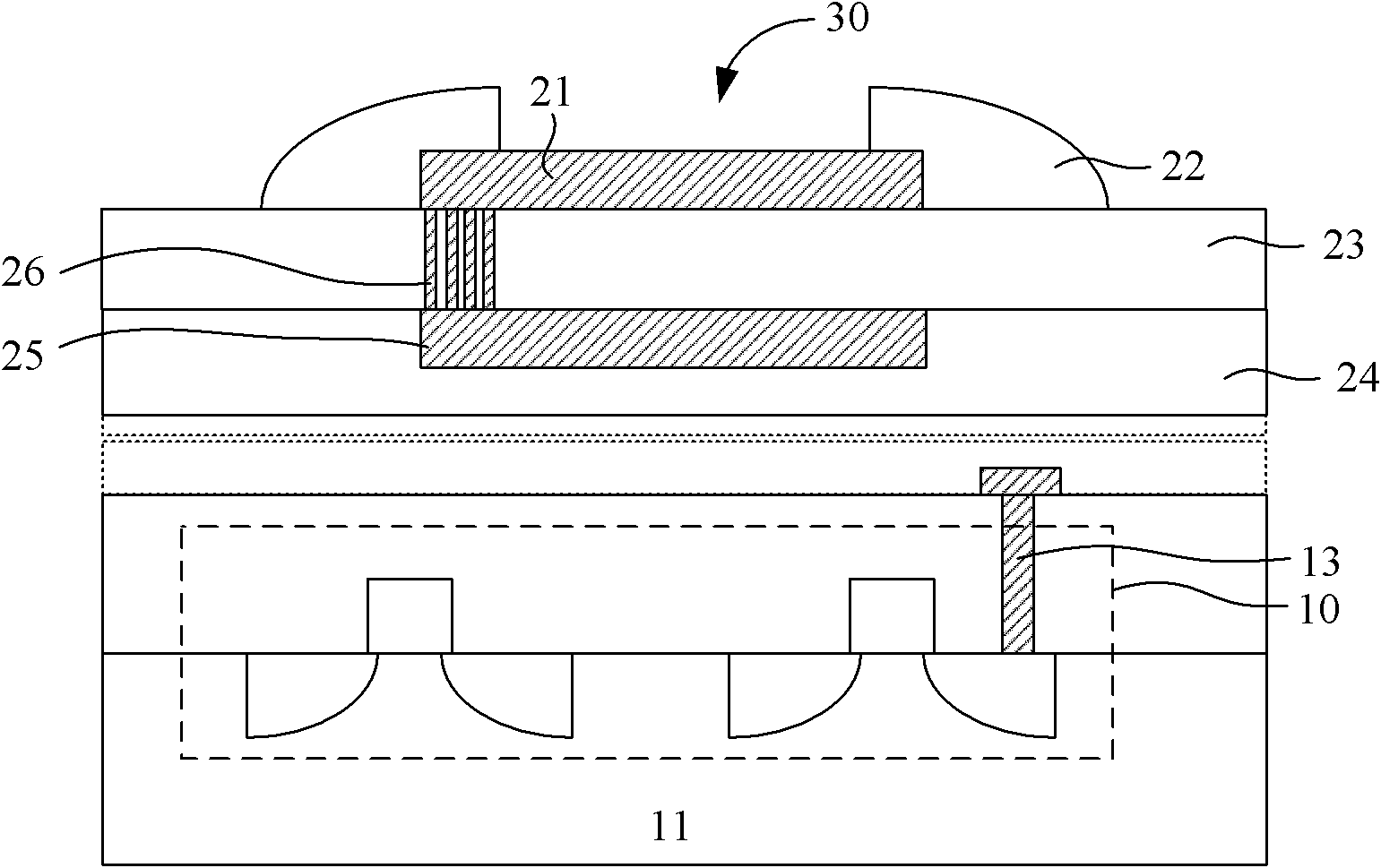
However, the above-mentioned structure has the following defects in the packaging process: during the CP test process, the probe touches the opening 30 of the bonding pad 21, and the mechanical pressure that is not easy to control is easy to cause damage to the bonding pad 30 and the metal lining below it. Pad, causing the metal pad to collapse; also in the package (Package) process, such as the package for copper wires, wire bonding or gold ball bonding (Gold Ball) and other bonding processes require a large bonding force, which cannot To avoid the need for external force, it is also easy to cause damage and collapse of the underlying metal pad, damage the effective circuit 10, and even cause redundant electrical connections between the collapsed metal pad 25 and the effective circuit 10, causing chip failure, resulting in failure of product testing and packaging. Lower yield rate affects mass production requirements

Method used


Image

  • Improved structure aimed at BOAC framework
  • Improved structure aimed at BOAC framework
  • Improved structure aimed at BOAC framework

Examples


Embodiment Construction

[0023] In order to make the content of the present invention clearer and easier to understand, the content of the present invention will be further described below in conjunction with the accompanying drawings. Of course, the present invention is not limited to this specific embodiment, and general replacements known to those skilled in the art are also covered within the protection scope of the present invention.

[0024] Secondly, the present invention is described in detail by means of schematic diagrams. When describing the examples of the present invention in detail, for the convenience of explanation, the schematic diagrams are not partially enlarged according to the general scale, which should not be used as a limitation of the present invention.

[0025] The embodiment of the present invention is explained according to the accompanying drawings. In the description of the present invention and the accompanying drawings, the figure shows the topmost layer of the metal lay...


PUM


Abstract

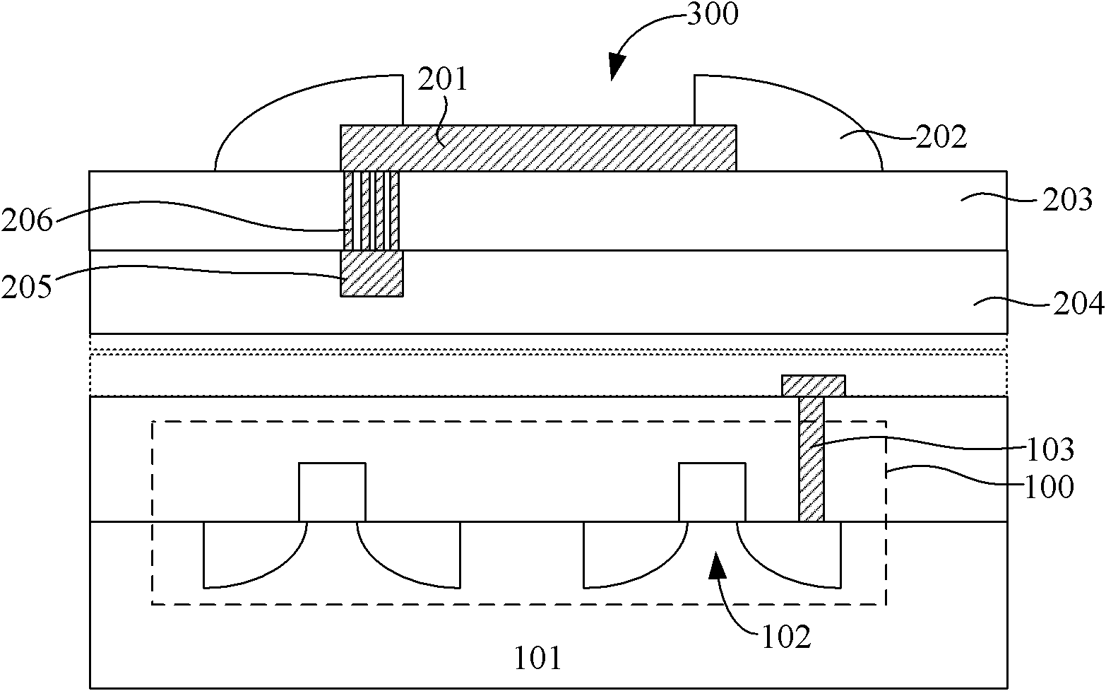
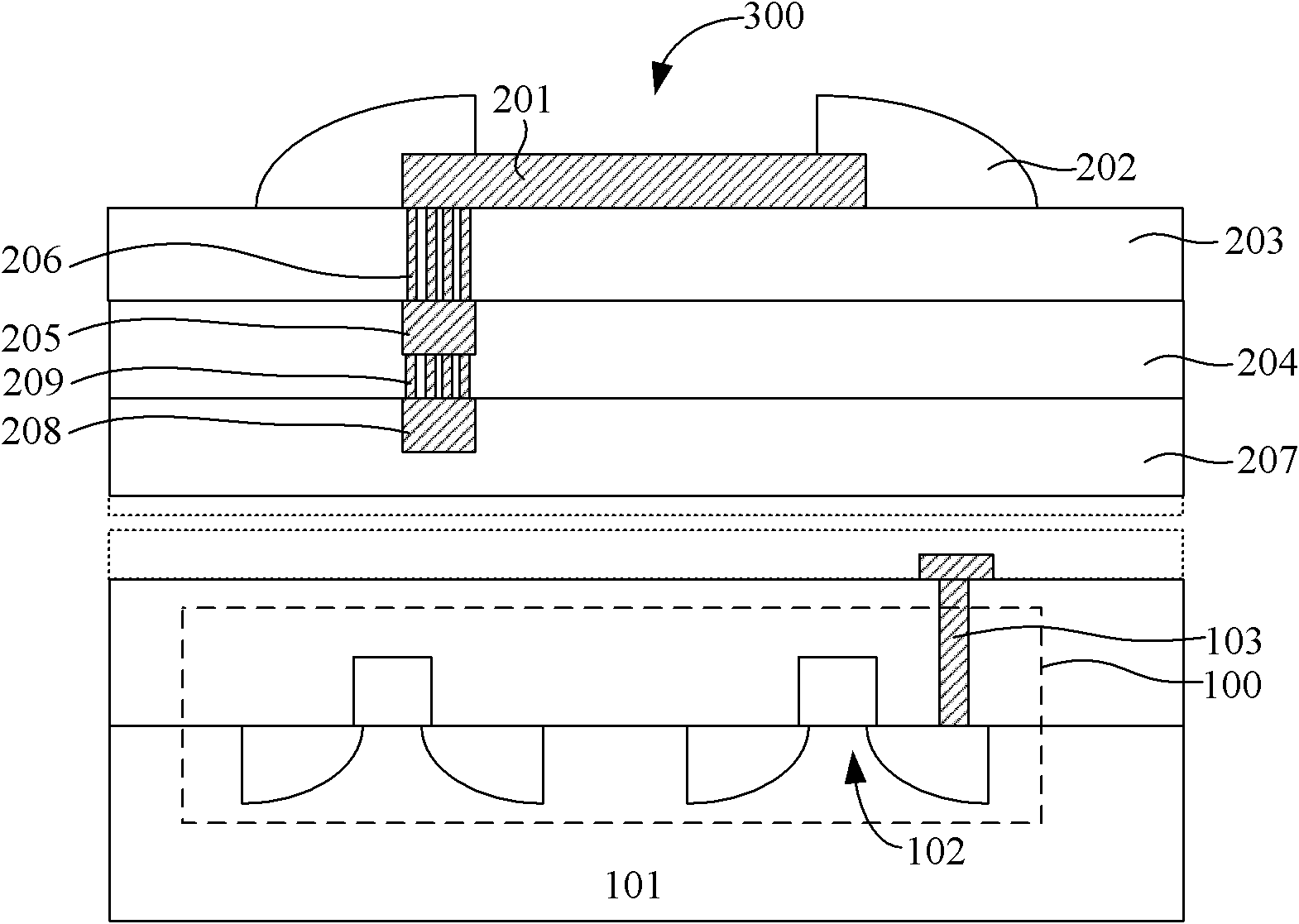
The invention provides an improved structure aimed at a BOAC framework, which comprises an active circuit and a bond pad structure arranged above the active circuit. The bond pad structure comprises a bond pad, a passivation layer, and a first metal gasket. The bond pad is arranged on a first dielectric layer; the passivation layer is covered on the periphery of the bond pad so as to form an opening area on above the bond pad; and the first metal gasket is arranged in a second dielectric layer and is arranged on the periphery of a corresponding right under the opening area. As an original metal gasket in an area right under the opening area of a bond pad of the prior art is changed into a dielectric medium material with larger mechanical strength by the improved structure, then mechanical pressure formed in the opening area during subsequent packaging process can be absorbed and born by the dielectric medium material; in this way, collapse of the bond pad and the metal gasket caused by external mechanical pressure can be effectively prevented so as to avoid the active circuit below from damaging; therefore, redundant electric property connection formed by the active circuit can be prevented; therefore, the failure rate of the active circuit is reduced, and the product yield is improved.

Description

technical field [0001] The invention relates to an integrated circuit manufacturing technology, and in particular to an improved structure for a BOAC framework. The improved structure can form a bonding pad structure on an active circuit (Active Circuit) that can withstand relatively large mechanical pressure. Background technique [0002] With the rapid development of the integrated circuit manufacturing industry, the circuit density and complexity of integrated circuits have increased significantly, and the package size has also decreased significantly. Advances in technology have been accompanied by increased demands for faster operation, cost reduction, and higher reliability of semiconductor devices. Forming more independent semiconductor chips on a wafer is very important to the above technical development requirements. [0003] In order to reduce the size of a chip (Chip), it is desirable to form a bonding pad (Bonding Pad) directly on an effective circuit. The BOAC...

Claims


Application Information

Patent Timeline
IPC IPC(8): H01L23/00H01L23/528H01L23/488
CPCH01L24/05H01L2224/02166H01L2224/04042H01L2224/05093H01L2224/45144H01L2224/48463H01L2924/1306H01L2924/13091H01L2924/14H01L2924/00
Inventor 王秉杰
Owner SINO WEALTH ELECTRONICS
Learn More