
A capacitor and a method of manufacturing the same

A technology of capacitors and dielectrics, applied in the field of capacitors, can solve problems such as trouble

Inactive Publication Date: 2011-07-20
NXP BV
View PDF1 Cites 8 Cited by
  • Summary
  • Abstract
  • Description
  • Claims
  • Application Information

AI Technical Summary

Problems solved by technology

[0005] However, the above method involves several process steps such as firing the raw material, grinding and mixing to form a coating solution, hardening the film, etc., which is cumbersome

Method used


Image

  • A capacitor and a method of manufacturing the same
  • A capacitor and a method of manufacturing the same
  • A capacitor and a method of manufacturing the same

Examples


Embodiment Construction

[0045] The illustrations in the figures are schematic. In different figures, similar or identical elements have the same reference signs.

[0046] figure 1 An integrated circuit 100 according to an example embodiment of the invention is shown.

[0047] The integrated circuit 100 is formed in a silicon process, ie, on a crystalline silicon substrate 102 . The integrated circuit 100 includes an integrated circuit portion 104 in which multiple integrated circuit components such as inductors, resistors, transistors, etc. may be monolithically integrated. Integrated circuit 100 also includes monolithically integrated capacitor 110 electrically coupled to integrated circuit component 104 via conductive trace 106 . Accordingly, capacitor 110 may interact with monolithic integrated circuit assembly 104 , eg, to form a resonant circuit, an oscillator circuit, a filter, a memory unit, or the like.

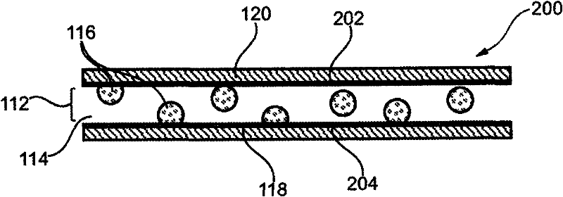
[0048]Capacitor 110 includes a thin film capacitor dielectric layer 112 formed from ...


PUM


Abstract

A capacitor (110), wherein the capacitor (110) comprises a capacitor dielectric (112) comprising a dielectric matrix (114) of a first value of permittivity, and a plurality of nanoclusters (116) of a second value of permittivity which is larger than the first value of permittivity which are at least partially embedded in the dielectric matrix (114), wherein the plurality of nanoclusters (116) are formed in the dielectric matrix (114) by spontaneous nucleation.

Description

technical field [0001] This invention relates to capacitors. [0002] Furthermore, the invention relates to a method of manufacturing a capacitor. Background technique [0003] A capacitor may refer to an electrical device that can store energy in an electric field between a pair of conductors (which may be referred to as plates). The process of storing energy in a capacitor, which can be called charging, involves the accumulation of equal and opposite charges on each plate. [0004] US 2006 / 0001069 discloses a composition for forming a dielectric layer having a suitable dielectric constant and capable of withstanding voltage characteristics. A MIM capacitor and its production process are disclosed. Provided is a composition for forming a dielectric layer, the composition includes perovskite type dielectric crystal particles, glass powder, and hydrolysable silicon compound (hydrolysable silliconcompound) and its oligomers, the MIM capacitor includes a substrate and sequen...

Claims


Application Information

Patent Timeline
Patent Type & Authority Applications(China)
IPC IPC(8): H01G4/10H01G4/12H01G4/20
CPCH01G4/10H01G4/20H01G4/1227
Inventor 古川有纪子吉内什·巴拉克里什纳·皮拉伊·库查普拉克尔约翰·亨德里克·克洛特威克弗兰克·帕斯威尔
Owner NXP BV
Learn More