
Power field effect transistor and layout method thereof

A power field effect, transistor technology, applied in the direction of electric solid device, semiconductor device, semiconductor/solid state device manufacturing, etc., to increase channel density, reduce on-resistance, reduce RDSON effect

Inactive Publication Date: 2011-06-29
SILERGY SEMICON TECH (HANGZHOU) CO LTD
View PDF3 Cites 6 Cited by
  • Summary
  • Abstract
  • Description
  • Claims
  • Application Information

AI Technical Summary

Problems solved by technology

Using this method, although the inherent channel resistance remains unchanged, the high density of the field effect transistor channel density can also reduce the on-resistance R of the field effect transistor DSON

Method used


Image

  • Power field effect transistor and layout method thereof
  • Power field effect transistor and layout method thereof
  • Power field effect transistor and layout method thereof

Examples


Embodiment Construction

[0052] Several preferred embodiments of the present invention will be described in detail below with reference to the accompanying drawings, but the present invention is not limited to these embodiments. The present invention covers any alternatives, modifications, equivalent methods and schemes made on the spirit and scope of the present invention. In order to provide the public with a thorough understanding of the present invention, specific details are set forth in the following preferred embodiments of the present invention, but those skilled in the art can fully understand the present invention without the description of these details.

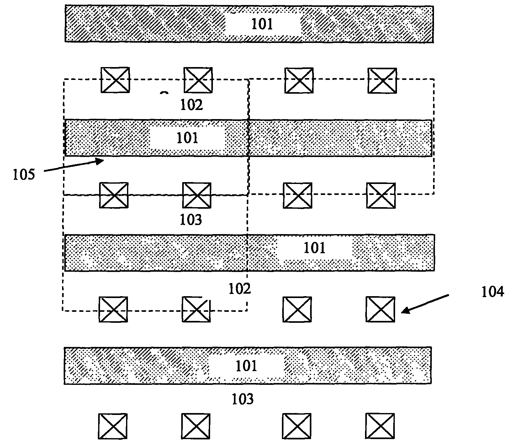
[0053] image 3 Shown is a schematic diagram of the layout structure of a unit cell of a field effect transistor according to an embodiment of the present invention. In this embodiment, the unit cell includes a drain region 301, a gate region 302 and a source region 303. part, and the drain region 301 and the source region 303 are distri...


PUM


Abstract

The invention relates to a power field effect transistor which is integrated on a single silicon slice and a layout method thereof. The power field effect transistor consists of a plurality of unit lattices which are arranged in parallel, wherein each unit lattice comprises a gate region, a source region and a drain region; and the drain region and the source region are distributed on the two sides of the gate region respectively. The power field effect transistor is characterized in that: the gate region is bent and bends towards the drain region at a first end to form a first concave region, a first bent region and a first contact region on the drain region; the gate region bends towards the source region at a second end to form a second concave region, a second bent region and a second contact region on the source region; by the bent gate region, an effective channel width is increased, so that on resistance RDSON is reduced; the corresponding drain region and source region are not rectangular any longer but have different shapes on different regions, so that the height of each unit lattice is reduced to further reduce the on resistance RDSON; and the channel density of the field effect transistor can also be increased, so that the on resistance RDSON is reduced. A method for implementing the field effect transistor is more favorable and practical.

Description

technical field [0001] The invention relates to a field effect transistor, more specifically, to a power field effect transistor integrated on a single silicon chip and a layout design method thereof. Background technique [0002] Behind the new power generation / energy-saving technologies and devices, high-frequency switching power converters play an extremely important role. High-frequency switching power conversion technology uses semiconductor power components to switch at high frequency, combined with various energy conversion components such as transformers, and energy storage components such as inductors and capacitors to meet the requirements of high efficiency and high power density. [0003] Power FETs are commonly used in portable and wireless products, and their applications include battery protection, load management, and DC-DC conversion. For these applications, the most important characteristic of a power FET is its drain-source on-resistance R DSON . R DSO...

Claims


Application Information

Patent Timeline
IPC IPC(8): H01L27/105H01L29/78H01L29/41H01L21/8232H01L21/336H01L21/768
Inventor 游步东
Owner SILERGY SEMICON TECH (HANGZHOU) CO LTD
Learn More