
Micro-electroforming method based on magnetic force-driven convection effect and device thereof

A technology of convection effect and magnetic field force, applied in the direction of electroforming, electrolysis, etc., can solve the problems of limited mass transfer in liquid phase, achieve the effect of strengthening auxiliary mass transfer, reducing deposition defects, and simple method

Inactive Publication Date: 2011-06-22
HENAN POLYTECHNIC UNIV
View PDF0 Cites 9 Cited by
  • Summary
  • Abstract
  • Description
  • Claims
  • Application Information

AI Technical Summary

Problems solved by technology

[0005] The present invention aims to solve the technical problem of severely limited liquid-phase mass transfer in the micro-electroforming process, and provides a micro-electroforming method and device based on the magnetic field force to drive the convection effect, which solves the problem of microstructure electroforming with a high aspect ratio (diameter) ratio. Due to the limitation of mass transfer in the liquid phase, the prepared electroformed parts have uniform thickness, less deposition defects and dense structure

Method used


Image

  • Micro-electroforming method based on magnetic force-driven convection effect and device thereof
  • Micro-electroforming method based on magnetic force-driven convection effect and device thereof
  • Micro-electroforming method based on magnetic force-driven convection effect and device thereof

Examples


Embodiment Construction

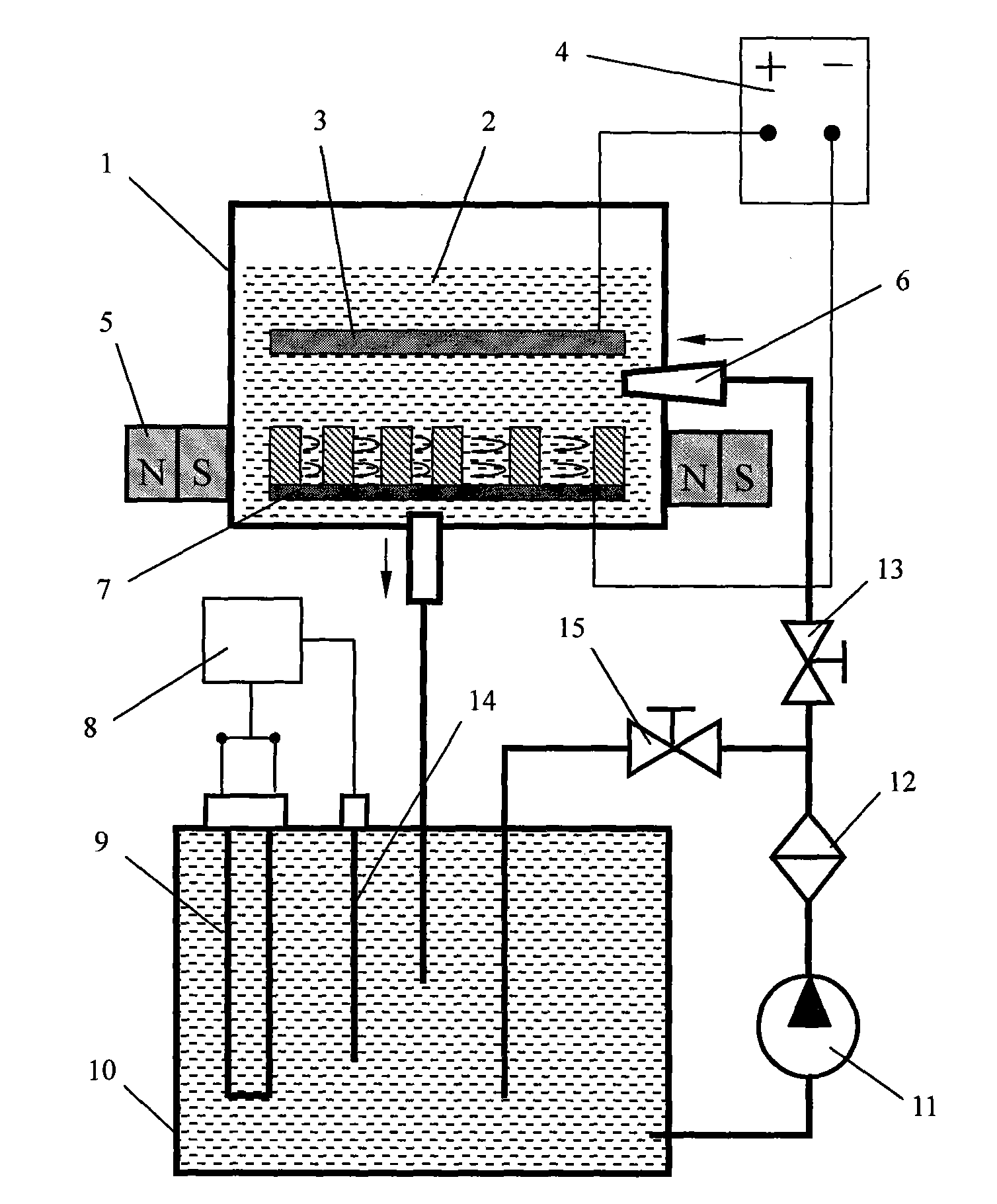
[0025] A micro-electroforming method based on the magnetic field force to drive the convection effect. First, the anode and cathode mandrels are placed in the electroforming tank, and then the electroforming solution is added to the electroforming tank, and the cathode and anode are connected to the power supply. When the mandrel is powered on After the casting layer reaches the specified thickness, the power is cut off, the liquid supply and electroforming are stopped, and the core mold is removed to remove the glue. During the electroforming process, a magnetic field perpendicular to the current direction between the cathode and anode is superimposed on the outside of the core mold.

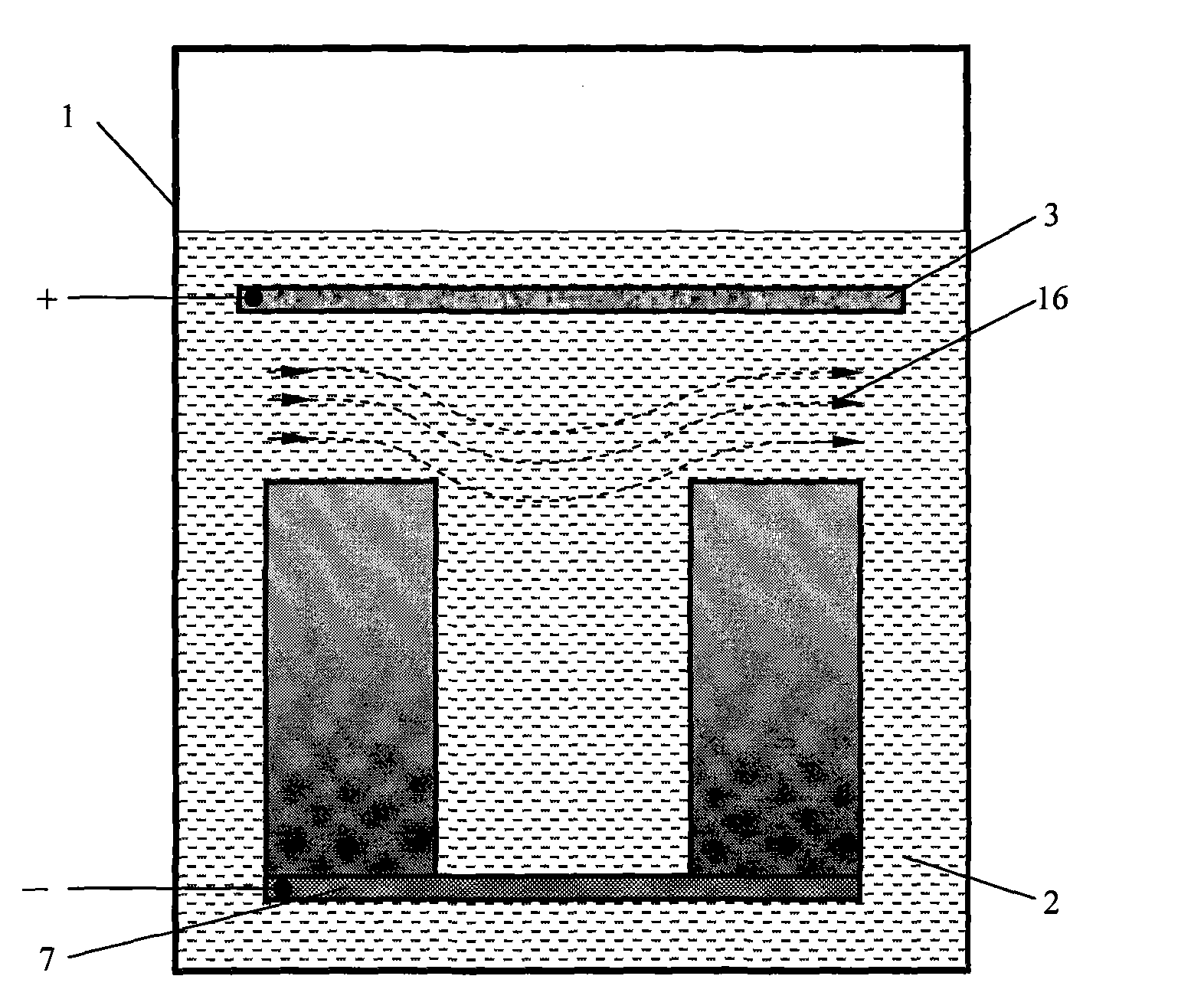
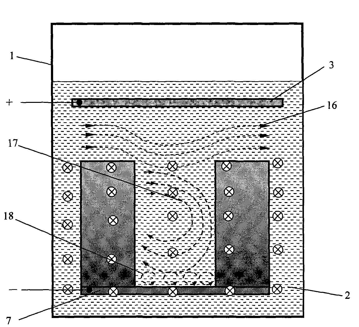
[0026] The principle of the present invention is as follows: After adding a magnetic field, a large number of charged electromotive particles in the electroforming liquid in the micro-deep hole / groove of the electroforming mandrel are therefore subjected to the strong Lorentz force, and the movem...


PUM


Abstract

The invention discloses a micro-electroforming method based on the magnetic force-driven convection effect and a device thereof, belonging to the electrochemical micromachining field. The method comprises the following steps: an anode and cathode core mould is placed in an electroforming groove, electroforming solution is added in the electroforming groove, the cathode and anode are electrified, when the electroforming layer on the core mould reaches a defined thickness, the solution supply and electroforming are stopped, the core mould is taken out to demould and remove photoresist; and in the electroforming process, a magnetic field perpendicular to the current direction of the anode and cathode is superposed on the outside of the core mould. The device used for implementing the method contains a electroforming system, an electroforming solution temperature control system and an electroforming solution circulating system, wherein the outside of the core mould in the electroforming system is provided with a magnetic field generator. By adopting the method of the invention, the problem that the liquid phase mass transfer of high depth-to-width ratio (depth-to-diameter ratio) micro-electroforming is limited can be solved; and the prepared casting has uniform thickness, fewer sedimentation defects and compact structure.

Description

technical field [0001] The invention belongs to the field of micro-electrochemical processing, and in particular relates to a micro-electroforming method and a device for implementing the method. Background technique [0002] Metal microstructures and parts are often the core of micro-electromechanical systems, micro-machines and high-tech products, directly affecting or even determining the service performance of the products they rely on. Microfabrication technology is the basis and premise for the realization of the above-mentioned microstructures and parts. The micro-electroforming technology based on the principle of electrochemical deposition has become one of the main supporting technologies in the field of metal micro-manufacturing due to its technological advantages such as high replication accuracy, high repeatability, wide material selection range, and low process operating temperature. For example, in the production of semiconductor products, copper wiring on pr...

Claims


Application Information

Patent Timeline
Patent Type & Authority Applications(China)
IPC IPC(8): C25D1/00
Inventor 明平美姜无疾李伟吕印定
Owner HENAN POLYTECHNIC UNIV
Learn More