Method of adjusting machine tool and machine tool

An adjustment method and machine tool technology, which is applied to the parts of boring machine/drilling machine, milling machine equipment, metal processing machinery parts, etc., can solve the problems of workpiece jumping and incomplete reach

Active Publication Date: 2011-06-15
WAIDA MFG
View PDF2 Cites 3 Cited by
  • Summary
  • Abstract
  • Description
  • Claims
  • Application Information

AI Technical Summary

Problems solved by technology

Due to this situation, the prior art floating chuck is the direct cause of workpiece runout
Therefore, the prior art has the problem that the object of the present invention cannot be fully achieved in eliminating the tiny runout of the workpiece in ultra-precision machining.

Method used


Image

  • Method of adjusting machine tool and machine tool
  • Method of adjusting machine tool and machine tool
  • Method of adjusting machine tool and machine tool

Examples


Embodiment Construction

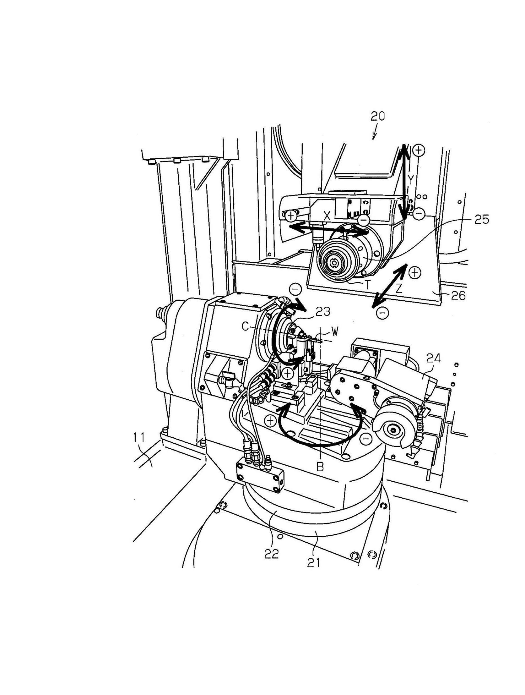
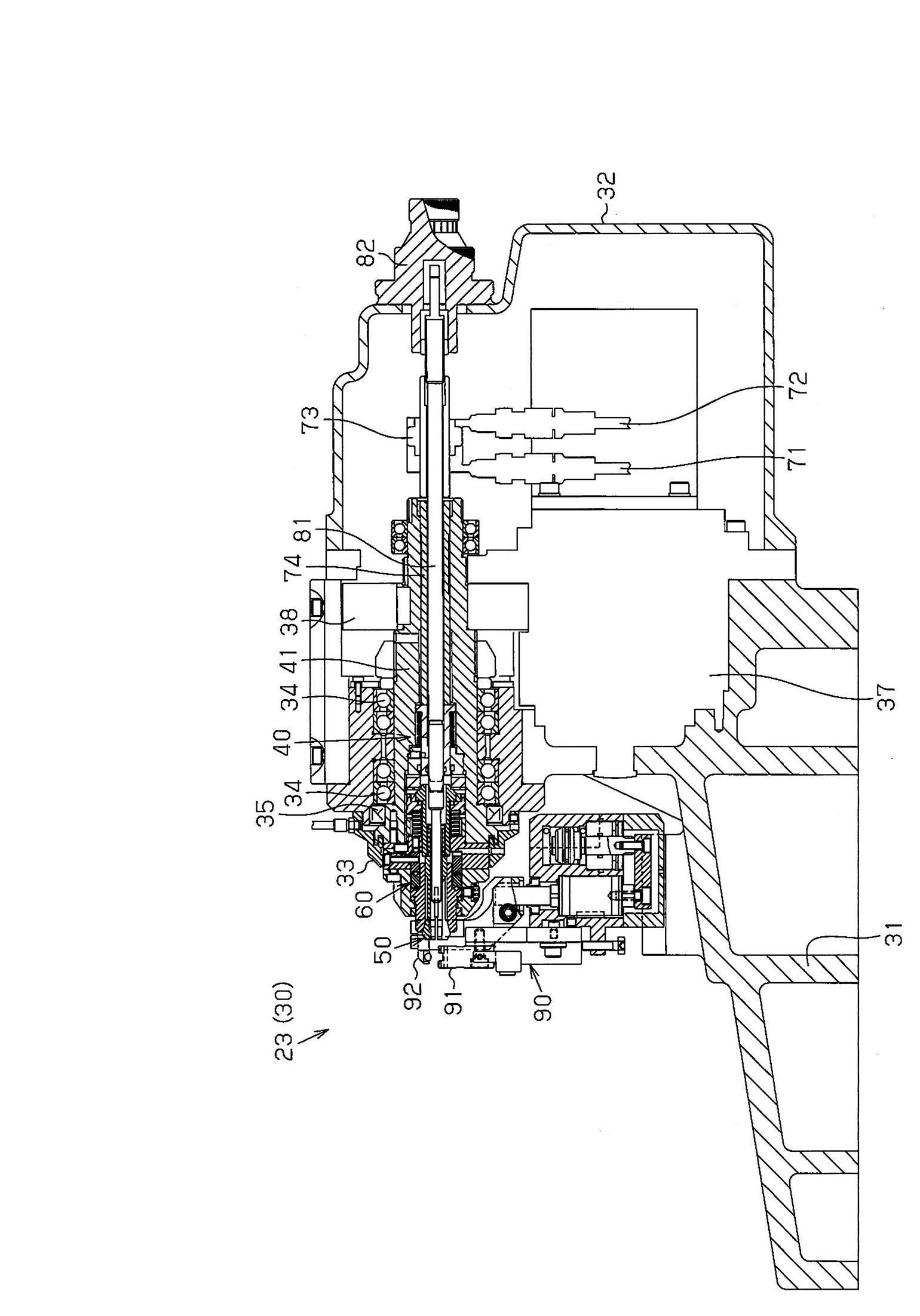
[0072] Figure 1-18 A tool grinder 20 according to a specific embodiment of the invention is described.

[0073] The tool grinder 20 according to the present application is a fully automatic computer numerical control (Computer Numeric Control, CNC) micro-diameter end milling grinder. The tool grinder 20 single-clamping tool fully automatically processes all the steps of end face grinding with small diameter (tool diameter between 0.01 and 2.0mm).

[0074]

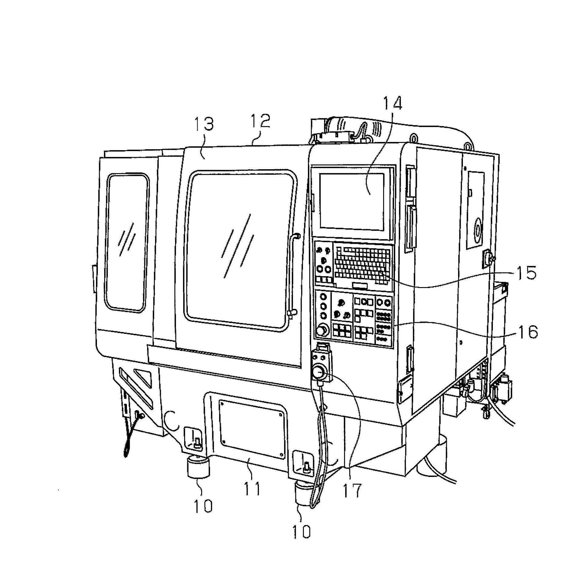
[0075] Such as figure 1 As shown, a tool grinder 20 is housed in an equipment housing 12 whose outer surface forms a box shape and is set on a shelf 11 supported by several bases 10 . The center of the front surface of the equipment housing 12 is provided with a front window 13 which has a window portion and can be selectively opened and closed to isolate the grinding machine 20 installed inside the equipment housing 12 . The front of the equipment casing 12 and the right side of the front window 13 are sequentially e...


PUM

PropertyMeasurementUnit
Diameteraaaaaaaaaa

Abstract

The invention provides a method of adjusting a machine tool. The method adjusts the machine tool so that, in ultra-precision machining of round bar-like work (W), the machine tool can rotate the work (W) while suppressing run-out of the axis of the work (W). In an axis position adjustment step (S5), a side surface of a projection portion of the work (W) held by a work holding mechanism (50) is measured while a work spindle (40) is rotated. A C-shaft adjustment screw (42b) is adjusted so that run-out of the work (W) is minimum and then the position of the work axis (C2) is fixed. In a support adjustment step (S6), with the position of the work axis (C2) fixed, a support block (91) is adjusted so as to support the work (W). In a support locking step (S7), the definition of the position of the work axis (C2) defined by the support block (91) is maintained by pressing the work (W) by a work presser (92). In a floating-restriction releasing step (S8), floating restriction by the C-axis adjustment screw (42b) is released.

Description

technical field [0001] The invention relates to a machine tool adjustment method and a machine tool, in particular to the centering adjustment of workpieces of tool grinding machines such as grinding and processing small-diameter end mills. Background technique [0002] In recent years, for ultra-precision machining tools, such as micro-diameter end mills with a diameter of about 0.01 to 1.00 mm, there has been an increasing demand for even more precise tool machining. Machining tools with such a small diameter requires mounting strip-shaped workpieces composed of cemented carbide and high-speed tool steel, etc., in the work chuck of the tool grinder. Then, the workpiece is ground while rotating it around the axis to form the desired shape of the tool. [0003] In this case, if the workpiece is supported by a cantilever method such as a collet chuck, the support of the workpiece becomes unstable. This creates vibrational noise when grinding the workpiece. That is, the wor...

Claims


Application Information

Patent Timeline
IPC IPC(8): B23Q1/64B24B3/06B24B3/26B23B31/36B24B3/24B24B41/06
CPCB24B3/06B23Q17/22
Inventor 藤井啓太北村弘志
Owner WAIDA MFG
Why Eureka
Try Eureka