
Device with schottky diode integrated in power metal oxide semiconductor (MOS) transistor and manufacturing method thereof

A technology of Schottky diodes and MOS transistors, which is applied in the field of semiconductor integrated circuit manufacturing, can solve the problems of increased chip area, insufficient process flow optimization, and high unit chip cost to achieve improved cross-frequency characteristics, low cost, and occupied area small effect

Active Publication Date: 2012-10-03
SHANGHAI HUAHONG GRACE SEMICON MFG CORP
View PDF0 Cites 0 Cited by
  • Summary
  • Abstract
  • Description
  • Claims
  • Application Information

AI Technical Summary

Problems solved by technology

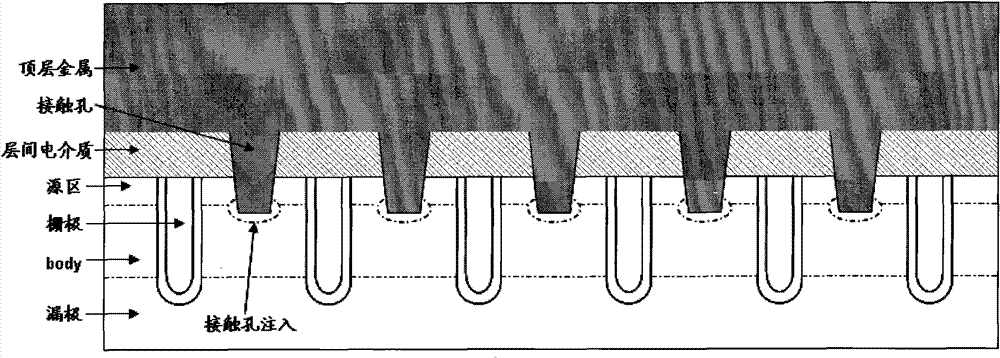
[0003] In order to improve the cross-frequency characteristics of the device, the current common method is to integrate a Schottky diode on the power MOS transistor chip, mostly a separate device, that is, a Schottky diode chip is connected in parallel next to the original power MOS transistor chip. Although this method It can improve the cross-frequency characteristics of the device, but there are disadvantages such as insufficient optimization of the process flow, increased chip area, and high unit chip cost.

Method used


Image

  • Device with schottky diode integrated in power metal oxide semiconductor (MOS) transistor and manufacturing method thereof
  • Device with schottky diode integrated in power metal oxide semiconductor (MOS) transistor and manufacturing method thereof
  • Device with schottky diode integrated in power metal oxide semiconductor (MOS) transistor and manufacturing method thereof

Examples


Embodiment Construction

[0024] The present invention will be described in further detail below in conjunction with the accompanying drawings and embodiments.

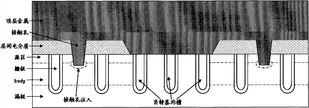
[0025] The device integrating Schottky diodes in the power MOS transistor mentioned in the present invention, on the basis of the original structure, nests several groups of Schottky contact trenches of specific structure between the gate trenches, the invention point of the main technology As shown in the following table:

[0026]

[0027]

[0028] Compare figure 1 , figure 2 , it can be clearly seen that the structure of the present invention skillfully forms a Schottky diode between the Schottky channels.

[0029] Such as Figure 3-Figure 7 Shown, the manufacturing method of the device of integrated Schottky diode in the power MOS transistor of the present invention, comprises the following steps:

[0030] In the first step, the gate channel 1 and the Schottky channel 2 are exposed and etched on the silicon substrate 3 (the depth...


PUM

PropertyMeasurementUnit
Depthaaaaaaaaaa

Abstract

The invention discloses a device with a schottky diode integrated in a power metal oxide semiconductor (MOS) transistor. Schottky grooves are formed between the regular grid grooves, and the schottky diodes are formed between the schottky grooves. Moreover, the invention also discloses a method for manufacturing the device, which comprises the following steps of: (1) etching grid grooves and schottky grooves on a silicon substrate, wherein the schottky grooves are between the formed grid grooves; (2) performing body injection and active injection into the schottky channel region with a photoresist barrier; (3) depositing an interlayer dielectric medium, exposing and etching a contact hole, and performing contact hole injection to form ohm contact; (4) exposing and etching schottky contact groove; (5) depositing metal, performing contact at the bottom of the schottky contact groove, metal and an epitaxial layer to form a schottky diode; and (6) performing subsequent processes including regular metal exposure, etching and alloying. The device improves the alternative frequency characteristics of apparatus on the premise of not increasing the chip area.

Description

technical field [0001] The invention relates to a semiconductor integrated circuit manufacturing technology, in particular to a device integrating a Schottky diode in a power MOS transistor, and also relates to a manufacturing process method of the device. Background technique [0002] In semiconductor integrated circuits, the existing typical power MOS (metal oxide semiconductor) transistor structure is as follows figure 1 shown. It controls the opening of the vertical channel through the channel gate to realize the switching function of the MOS tube. [0003] In order to improve the cross-frequency characteristics of the device, the current common method is to integrate a Schottky diode on the power MOS transistor chip, mostly a separate device, that is, a Schottky diode chip is connected in parallel next to the original power MOS transistor chip. Although this method It can improve the cross-frequency characteristics of the device, but there are disadvantages such as in...

Claims


Application Information

Patent Timeline
IPC IPC(8): H01L27/06H01L21/8249
Inventor 邵向荣魏炜
Owner SHANGHAI HUAHONG GRACE SEMICON MFG CORP
Learn More