
Microwire wire drawing machine for aluminum-silicon bonding wire

A wire drawing machine and micro-technology, applied in the field of metal wire drawing equipment, can solve the problem that the direction of wire movement is not perpendicular to the center of the die hole, etc., and achieve high production efficiency, quality assurance, and a smooth and straight surface.

Inactive Publication Date: 2011-05-11
THE NORTHWEST MACHINE
View PDF0 Cites 3 Cited by
  • Summary
  • Abstract
  • Description
  • Claims
  • Application Information

AI Technical Summary

Problems solved by technology

[0003] The technical problem to be solved by the present invention is to provide a micro-wire drawing machine for silicon-aluminum wire, which has a reasonable structural design and high production efficiency, and at the same time solves the problem that the moving direction of the wire is not perpendicular to the center of the die hole. problem, and ensure the surface quality of the wire

Method used


Image

  • Microwire wire drawing machine for aluminum-silicon bonding wire
  • Microwire wire drawing machine for aluminum-silicon bonding wire

Examples


Embodiment Construction

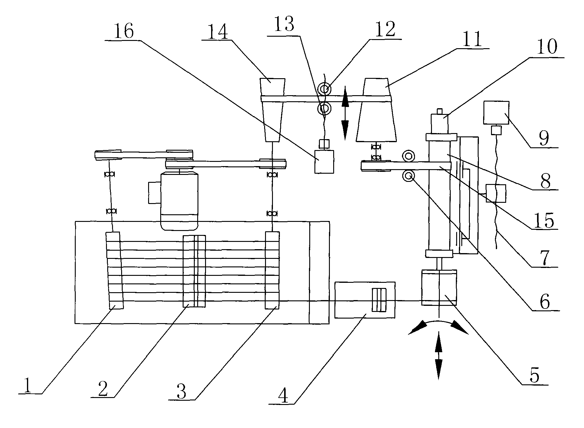
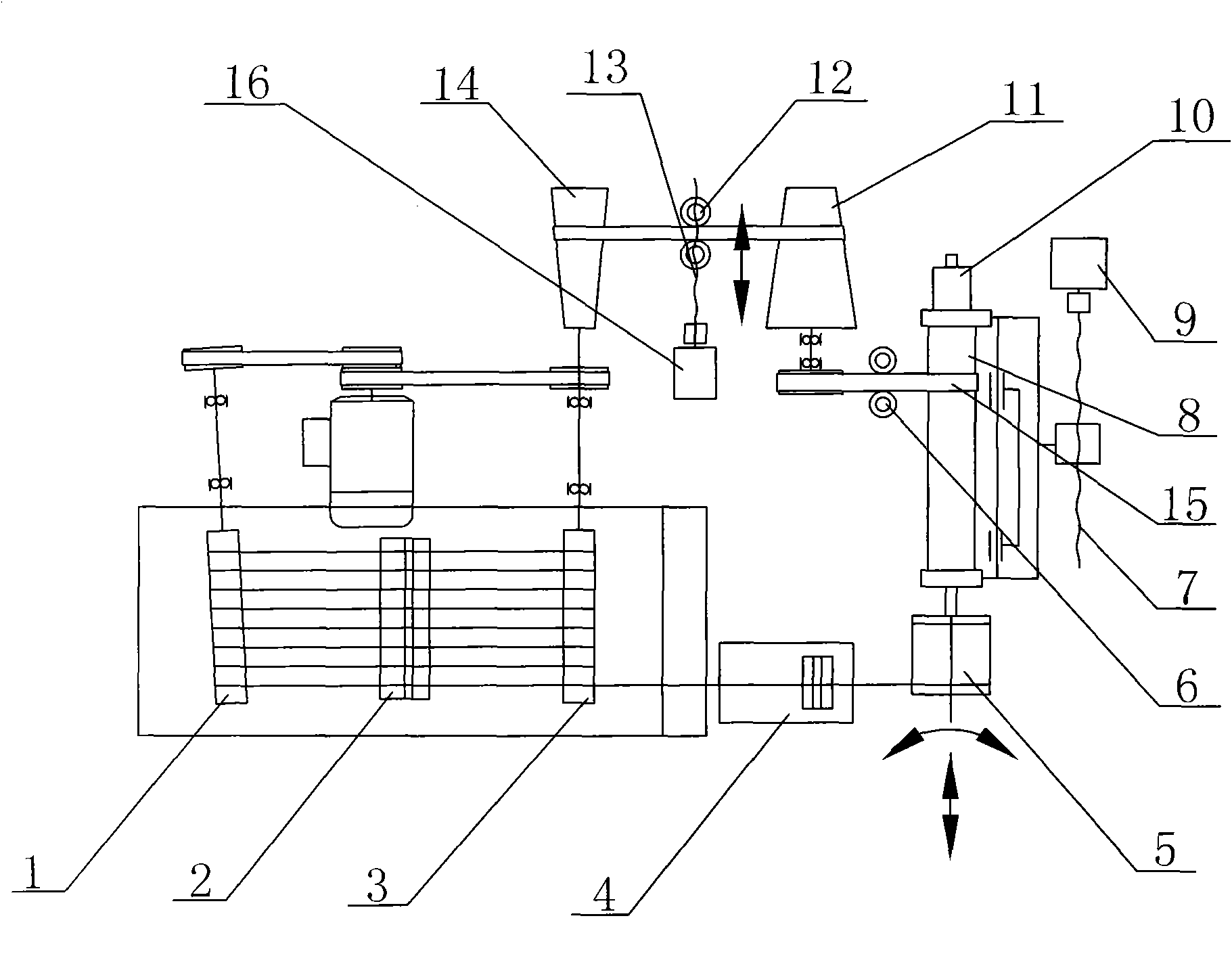
[0020] like figure 1 , a wire drawing machine for silicon-aluminum wire of the present invention includes a transmission system, a wire drawing mechanism and a wire receiving and discharging device, and the wire drawing mechanism is composed of a godet roller 1, a wire drawing die base 2, and a wire drawing roller 3 arranged in the horizontal direction in sequence. It is composed of a trimming die base 4, and the godet roller 1 and the wire drawing roller 3 form an angle of 1 to 5° inwardly in the horizontal direction. The winding wheel 5 and the encoder 10 are composed of the lower end and the upper end of the winding and discharging main shaft 8, and the winding power of the winding and discharging device is provided by a servo motor 16 arranged on one side of the winding and discharging device. The belt 15 transmits, and the power of the cable take-up and discharge device is provided by the stepping motor 9 arranged on the other side of the said take-up and discharge device...


PUM


Abstract

The invention discloses a microwire wire drawing machine for an aluminum-silicon bonding wire. The microwire wire drawing machine comprises a transmission system, a wire drawing mechanism and a take-up and winding device, wherein the wire drawing mechanism consists of a wire guiding roller, a wire drawing die holder, a wire drawing roller and a finishing die holder which are arranged in the horizontal direction sequentially, and the wire guiding roller and the wire drawing roller form a certain included angle inwards in the horizontal direction; the take-up and winding device consists of a take-up and winding main shaft and a take-up wheel and an encoder which are respectively arranged at the lower end and upper end of the take-up and winding main shaft, the take-up power of the take-up and winding device is provided by a servo motor arranged on one side of the take-up and winding device and is transmitted by a wire winding flat belt, and the winding power of the take-up and winding device is provided by a stepping motor arranged on the other side of the take-up and winding device and is transmitted by a ball-screw pair; and the transmission system comprises a flat belt moving screw rod and a driving conical pulley and a driven conical pulley which are arranged at the left end and right end of the flat belt moving screw rod. The microwire wire drawing machine has a reasonable structure and design and high production efficiency, solves the problem that the motion direction of the wire is not perpendicular to the center of a die hole simultaneously, and guarantees the surface quality of the wire.

Description

technical field [0001] The invention belongs to metal wire drawing equipment, in particular to a silicon-aluminum wire micro-wire drawing machine used for bonding wire materials in the manufacture of IC chips. Background technique [0002] With the rapid development of the manufacturing of microelectronic devices such as large-scale integrated circuits, hybrid circuits, microwave devices and separation devices, and the continuous improvement of technical requirements for IC chips with high density, high cleanliness, high uniformity, high strength and high packaging density , in the post-process of manufacturing microelectronic devices, the miniaturization of IC devices makes the contact and interconnection requirements of bonding wires more and more stringent, and the amount of fine bonding wires is also increasing with the development of IC chip micro-manufacturing technology. bigger. At present, due to the unreasonable design of the structure of the wire drawing machine i...

Claims


Application Information

Patent Timeline
IPC IPC(8): B21C1/02
Inventor 蔡小让马永康张青明
Owner THE NORTHWEST MACHINE
Learn More