Motor control device

A motor control and motor technology, applied in the direction of controlling electromechanical transmission, control system, control generator, etc., can solve problems such as motor out of step, and achieve the effect of suppressing rapid changes

Active Publication Date: 2011-04-20
KK TOSHIBA
View PDF5 Cites 2 Cited by
  • Summary
  • Abstract
  • Description
  • Claims
  • Application Information

AI Technical Summary

Problems solved by technology

As a result, the motor loses step and stops

Method used


Image

  • Motor control device
  • Motor control device
  • Motor control device

Examples


no. 1 Embodiment

[0030] Below, refer to Figure 1 to Figure 9 The first embodiment will be described. Figure 7 It is a plan view showing the structure of the rotor of the permanent magnet motor 1 (outer rotor type brushless motor). A permanent magnet motor 1 is composed of a stator 2 and a rotor 3 provided on its outer periphery. The stator 2 is composed of a stator core 4 and a stator winding 5 . The stator core 4 is formed by laminating and caulking a plurality of die-cut silicon steel sheets as soft magnetic materials, and has an annular yoke portion 4a and a plurality of radially protruding from the outer peripheral portion of the yoke portion 4a. a tooth portion 4b. The surface of the stator core 4 is covered with PET (polyethylene terephthalate: polyethylene terephthalate) resin (filling resin) except the front end surface of each tooth portion 4b.

[0031] In addition, a plurality of mounting portions 6 made of the PET resin are integrally formed on the inner peripheral portion of ...

no. 2 Embodiment

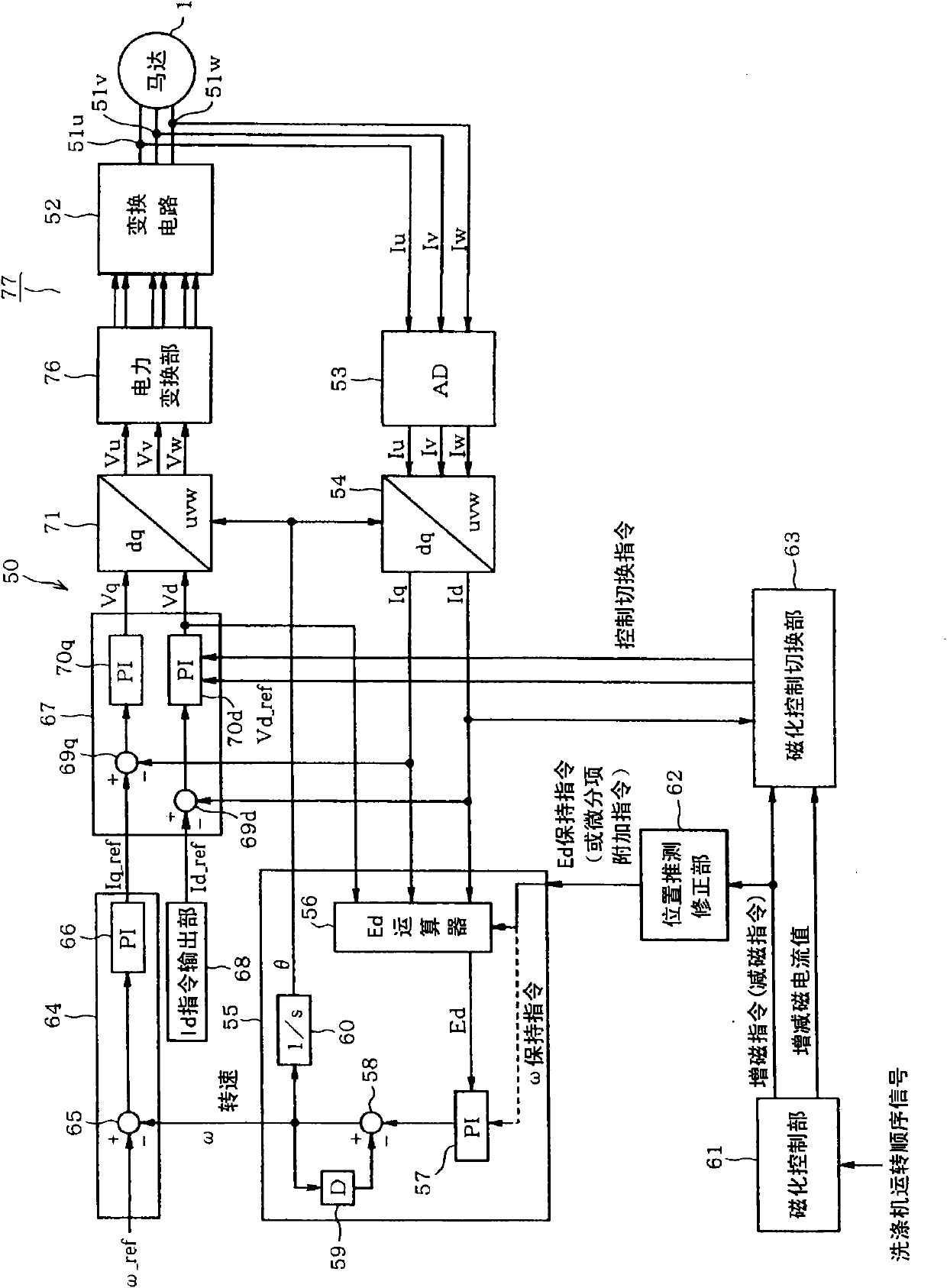
[0085] Figure 10 This is the second embodiment, showing the case where the motor control device 50 of the first embodiment is applied to an air conditioner (air conditioner). A compressor (load) 102 constituting the heat pump 101 is configured by accommodating a compression unit 103 and a motor 104 in the same iron airtight container 105 , and the rotor shaft of the motor 104 is connected to the compression unit 103 . Furthermore, the compressor 102, the four-way valve 106, the indoor side heat exchanger 107, the decompression device 108, and the outdoor side heat exchanger 109 are connected by pipes serving as refrigerant passages so as to constitute a closed cycle. In addition, the compressor 102 is, for example, a rotary compressor, and the motor 104 is a permanent magnet motor having the same configuration as the motor 1 of the first embodiment.

[0086] During heating, the four-way valve 106 is in the state indicated by the solid line, and the high-temperature refrigera...


PUM

PropertyMeasurementUnit
Coercivityaaaaaaaaaa

Abstract

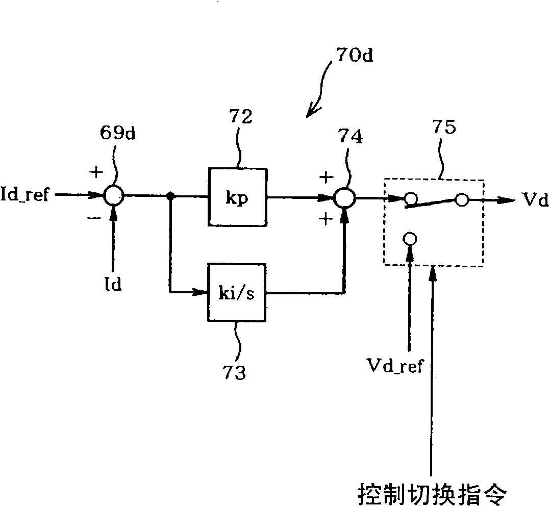
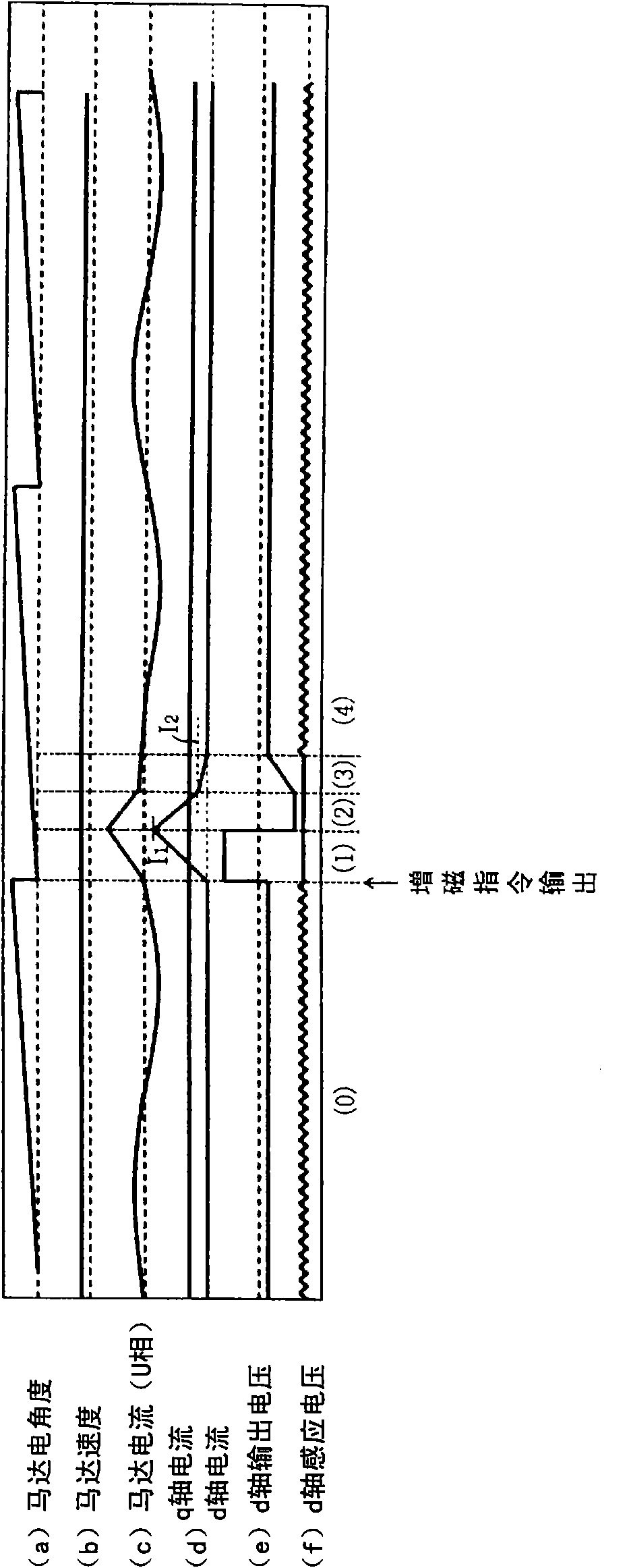
The invention provides a motor control device; in a structure for controlling a permanent magnet motor by a method without a position sensor and electrifying to change the flux of the permanent magnet, the motor is not controlled by means of stepping out. A motor control device (50) infers the rotation position (theta) of a rotor (3) according to a voltage equation founded to a permanent magnet motor (1) through a speed position inferring part (55), and d-axis current and q-axis current are calculated according to the inferred rotation position (theta), thereby performing a vector control to the permanent magnet motor (1). Moreover, during a period that a magnetization control part (61) electrifies the winding (5) of the motor (1) via a conversion circuit (52) to magnetize an aluminum-nickel-cobalt magnet (9b), a position inferring correction part (62) temporarily replaces the calculated result obtained by the voltage equation to a fixed value, thereby correcting the inferred rotationposition (theta).

Description

technical field [0001] The present invention relates to a motor control device provided with a mechanism capable of adjusting the magnetization state of a low-coercivity permanent magnet arranged in a rotor of a permanent magnet motor by an armature reaction magnetic field. Background technique [0002] In recent years, in washing machines, the combination of a direct-drive permanent magnet motor and a motor control device using vector control has improved the control accuracy of the motor and improved washing performance, and achieved reductions in power consumption and improved efficiency during washing operations. Effects such as vibration reduction. In a conventional general control method, when the motor is rotated at high speed during dehydration operation or the like, field weakening control is performed to reduce the induced voltage of the motor by passing a d-axis current Id that does not contribute to torque. In this case, during the spin-drying operation, a curre...

Claims


Application Information

Patent Timeline
IPC IPC(8): H02P21/00H02P21/14H02P21/18H02P21/24H02P21/28H02P27/04
CPCH02P21/14H02P21/18H02P21/26H02P27/04H02P2203/03H02P2207/05
Inventor 前川佐理
Owner KK TOSHIBA
Why Eureka
Try Eureka